Imaging
Contents
Executing an imaging script
Unlike spectroscopic observations which require two scripts per MODS, one for acquisition and another for the observation, imaging observations require only one script. The imaging script contains both the preset and the observation blocks. A sample imaging script may be found on the MODS Scripts page.
Monocular
If you are using just one MODS, the command:
execMODS --modsN imgscr.txt will execute the script imgscr.txt on whichever MODS is indicated by the command line option, –modsN. You can watch script progress in the terminal window.
Binocular
If you are using both MODS1 and MODS2, then run the shell-script wrapper, execBinoMODS, which will launch two terminal windows, one for MODS1 and the other for MODS2, in which you can watch the script progress.
execBinoMODS imgscr1.txtwill send the script imgscr1.txt to both MODS1 and MODS2; and
execBinoMODS imgscr1.txt imgscr2.txtwill send the script imgscr1.txt to MODS1 and imgscr2.txt to MODS2.
Wait for collimation
The script will pause when it reaches the WFSwait command. At this time, the observer should check the wavefront error (WFE) as reported on the GCSGUI. When the WFE drops below ~400nm, indicating that the telescope is collimated, then the observer should hit <Enter> so the script can continue
Binocular offsets: asynchronous vs synchronous
Imaging observations usually are dithered to mitigate the effects of bad pixels. Special care must be taken when designing dithering patterns for binocular observations.
Unless prefaced by a “syncoffset” script command, MODS will interpret offsets to be asynchronous. Asynchronous offsets are made through mirror, not mount, motions and are, therefore, limited by the mirror limits of travel and any additional travel used up by collimation.
Either each offset must be small enough that each side remains within the 40″ radius copointing limit, or a syncoffset command must precede the offset in order for it to be executed as a synchronous offset. Synchronous offsets may be larger than 40″ but they must not drive the two sides apart by more than twice the copointing radius.
However, because the scripts on MODS1 and MODS2 run independently, and overheads can significantly slow one side with respect to the other, synchronous offsets should not be used in MODS imaging scripts except perhaps for the first offset, if it is needed to move the target away from the center and into one of the quadrants. But note that this can also be accomplished by adjusting the target coordinates, and this method has the advantage of insuring that this relatively large initial offset will not move the guide probe out of the patrol field.
Special Considerations
PIs should consider the spatially-dependent PSF, saturation effects and the elevated background levels due to nearby stars when preparing their program and planning their observing strategy. However, these topics are, for now, discussed here where they may also benefit observers carrying out imaging observations.
Image Quality
The off-axis collimator mirrors produce field-dependent astigmatism. Further than 2.5 arcmin off-axis, the aberrations are severe. MODS produces its best images within 2 arcmin of the field center, and within 1 arcmin of the center, the delivered PSF is essentially undegraded. The ellipse plots below (Figure 1) and the pair of MODS1 Red and Blue images below that (Figure 2) illustrate the field-dependent astigmatism.
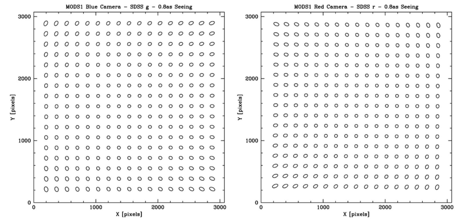
Figure 1: Ellipse plots for a pair of MODS1 Blue (g_sdss) and MODS1 Red (r_sdss) channel images taken when seeing FWHM was ~0.8″, as measured near the image center. (Taken from the MODS1 Commissioning Report).
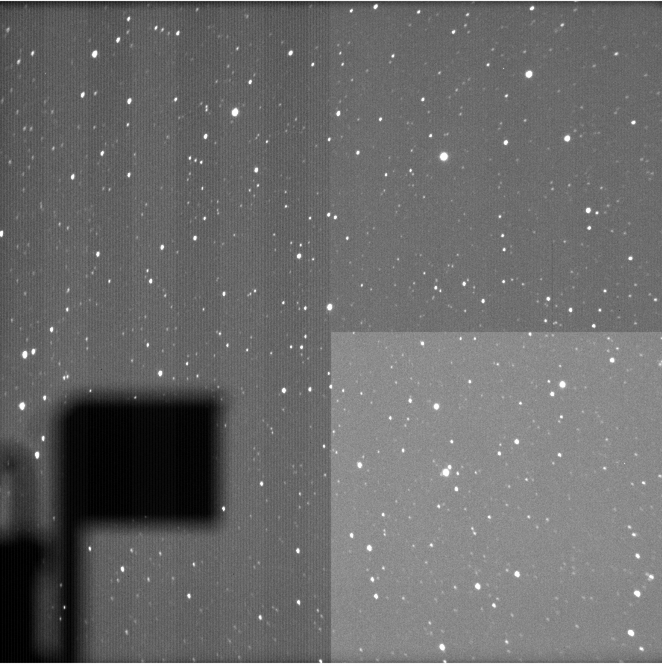
Figure 2: A pair of 3K x 3K (6 arcmin x 6 arcmin) MODS1 Blue (above) and Red channel (below) images of a field close to the Galactic plane, which illustrate the field-dependent aberrations. (The shadow at the bottom left is from the guide camera pickoff mirror and cables).

Saturation effects
The four MODS detectors respond differently to saturated stars or objects. On MODS1 Blue and MODS2 Red, trails extend from saturated stars to the middle rows, and on subsequent images, the trails extend from the locations of these stars on the first image to the top or bottom of the detector. Dither patterns need to take into account these persistent trails.
On all four MODS detectors, if a saturated star lands on the vertical quadrant boundary, the counts along the rows where the star falls will be ruined.
Examples of saturation effects are shown on the MODS Image Artifacts and Features page.
Stray light arcs
Light from bright, V less than ~5th magnitude, stars within a ~1.9-4 degree annulus about the field center can pass directly into MODS; the undersized adaptive secondary, without a baffle, does not shield the instrument from this light. As a result, images of fields with bright stars within this annular region, will show arcs of elevated background emission whose outer edge is defined by a stop within MODS and whose inner edge, by the edge of the adaptive secondary. The “stray light arcs” move as the instrument rotates and differ between the Blue and Red channels.
The deeper the image, the fainter are the stars which may produce these arcs. Ultimately, the lack of baffling around the adaptive secondary elevates the background emission and can degrade the sensitivity of MODS.
A web-based vizier search or, if you have cdsclient installed, the command:
vizquery -mime=text -source=V/50 -c=Jhhmmss.sss+ddmmss.ss -c.rm=114-240 -out.add='_r _raj2000 _decj2000' -out.max=unlimited -oc.form=d Vmag=0..5will query the Bright Star Catalog for stars with V=0-5 in an annulus 114-240 arcmin about the coordinates hhmmss.ss and ddmmss.ss at center.
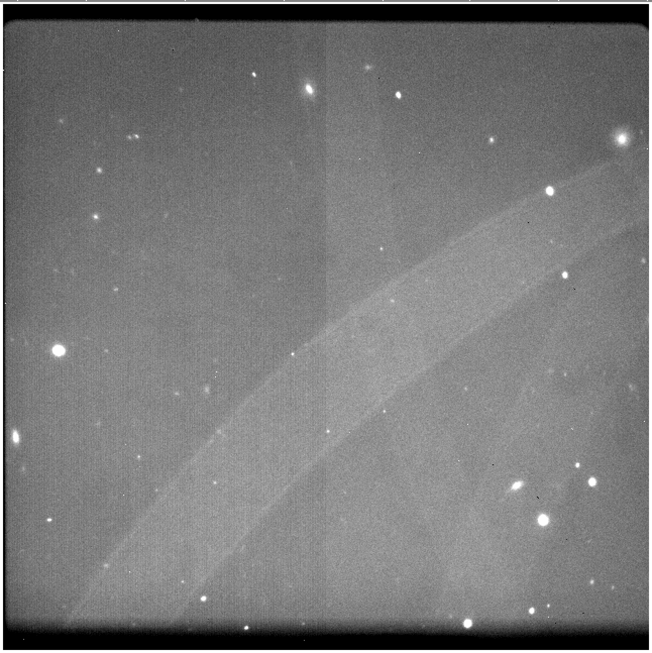
The image below shows a couple of “stray light arcs” and more examples are provided on the MODS Image Artifacts and Features page.
Figure 3: A 120-sec MODS2 Red channel image through the r_sdss showing 3 stray light arcs.