MOS spectroscopy
- The acquisition script slews the telescope, positions the guide probe, configures the instrument for imaging and takes the sequence of mask and field images which are needed to align the mask. The script then pauses as the observer runs modsAlign. Once the offset is applied, a final thru-mask confirmatory image is taken. If needed, final adjustments may be made through the MODS User Interface.
- The observation script moves the grating or prism into the beam and takes the series of spectroscopic exposures.
Acquisition
Monocular
acqMODS –modsN modsacq.txt will execute the script, modsacq.txt, on modsN, where N is either 1 or 2.
As each script command is sent and executed, output will be written to the terminal window and and changes will appear on the Dashboard of the MODS GUI.
If you are using both MODS1 and MODS2, then run the binocular wrapper, acqBinoMODS:
The script will pause after the mask and field images have been taken. At this point, the observer needs to run modsAlign.
From a separate terminal window, type (note that you can copy/paste the image filenames from the modsDisp or mods2Disp log into the modsAlign command line):
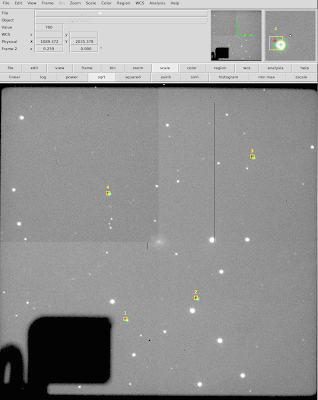
On the mask image, the positions of the alignment boxes will be automatically determined using the mms file and an edge-finding algorithm. Outlines based on these fits will be drawn in cyan (as shown below), and the observer will be asked to review the alignment boxes and accept them (‘a’), reject them and select them manually (‘m’) or abort (!).

‘a’ = accept all alignment boxes shown and continue
‘m’ = reject all alignment boxes and select boxes manually
‘!’ = abort modsAlign and exit the program now
Option: (a|m|!)?:
Usually, the fits are good, and ‘a’ is indicated, in which case the box centers are saved and the field image is displayed.
The option, ‘m’, might be needed if, for instance, a new guide star, which caused one of the boxes to be vignetted, had to be selected on-the-fly. If ‘m’ is selected, the observer is presented with the following options for selecting the alignment boxes. When finished, enter ‘q’ to save the choices and display the field image.
Commands:
‘a’ select the alignment box nearest the cursor
‘x’ select the alignment box at the current cursor XY position
‘d’ delete the previously selected box nearest the cursor
‘q’ quit alignment box selection and save choices
‘!’ abort alignment box selection and exit modsAlign now
‘?’ list interactive cursor commands
You must select at least two (2) alignment boxes, and the
cursor must be inside the box being marked.
Measuring the alignment star centroids
Once the box centers have been determined, the field image is displayed. The alignment stars are automatically found and their centroids measured. The observer is then given the choice of:
- ‘a’: accepting the centroids for all of the stars;
- ‘e’: editing one or two stars. This could be used if one of the alignment stars was not automatically found or to delete an alignment star which would be an outlier, e.g. a star whose position had not been corrected for proper motion;
-
- Edit alignment stars and press ‘q’ when done.
‘a’ add the star nearest the cursor with centroid calculation
‘x’ add a star at the current cursor XY position
‘d’ delete the star nearest the cursor
‘r’ change the star search radius [currently 15.0 pix]
‘q’ quit editing and save changes
‘!’ abort editing, discard all changes, and continue
‘?’ shows a list of all cursor commands
- Edit alignment stars and press ‘q’ when done.
- ‘m’: rejecting all of the alignment stars in order to select them manually. The menu in this case is the same as for the ‘e’ option above.
Review the alignment stars shown on ds9:
‘a’ = accept all alignment stars and continue
‘e’ = edit the alignment stars then continue
‘m’ = reject all alignment stars and select stars manually
‘!’ = abort modsAlign and exit the program now
Option: (a|e|m|!)?:
Sending the offset
to the telescope, followed by the updatepointing command which will cause the pointing origin to be updated such that the position of the target after the offset will become the new reference position. Absolute offsets will be made with reference to this new position.
dX = -1.667 arcsec
dY = 1.236 arcsec
dPA = -0.078 degMODS1 Offset Command:
offsetpointing -0.0782 -1.667 1.236 detxy relSend this offset to the telescope (Y|N)?: Y
The offset is complete when the prompt reappears in the terminal window and the “Offset” button in the MODS User Interface changes from an amber to grey background.
Taking the confirmatory thru-slit image
After the offset is complete, type <Enter> in the script-running window(s) to resume the script. The mask will be inserted again into the focal plane, and the thru-slit confirmatory image will be taken.
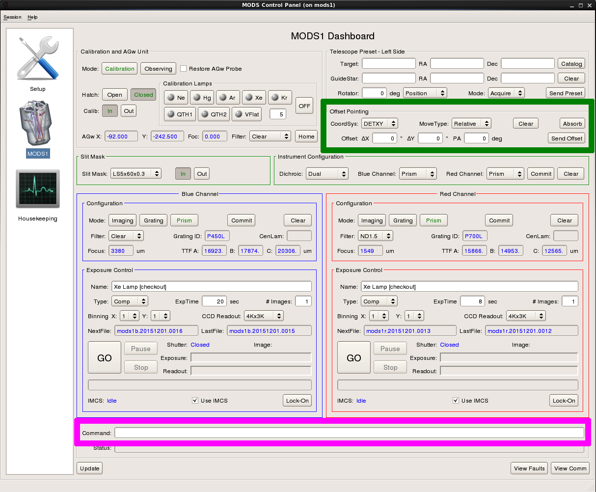
Often the offset sent by modsAlign does not perfectly center the target in the slit. Use the Offset Pointing section of the MODS User Interface (indicated by the green rectangle in the figure below) to make tweaks:
- Click the button “Clear” to clear any entries for dx, dy or dtheta offsets.
- Make sure the “CoordSys” is DETXY and the “MoveType” is “Relative”.
- Enter the desired deltaX and deltaY offsets in arcseconds
- (delta theta if needed, but it is difficult to tweak this and usually only deltaX, deltaY adjustments are made).
- Pixel scales are 0.12″/pix for the Blue and 0.123″/pix for the Red camera
- Click “Send Offset” to send the offset command to the telescope.
- Remember to click “Absorb” after this to update the pointing origin in the DETXY system. (Note that the spectroscopic observation scripts have an “updatepointing” command as the first item in the “Exec” block, but it doesn’t hurt to do it twice.)
Observation
Now that the object is well-centered on the slit, run the observation script to configure the instrument for grating or prism spectroscopy and take the sequence of spectra.
Monocular
If you are using just one MODS, then, in a terminal window, run the monocular command, execMODS:
Binocular
If you are using MODS1 and MODS2, then use the shell script wrapper, execBinoMODS.
Taking a few more exposures
If a few more exposures are needed, to account for poorer-than-expected seeing or transparency, then it is preferable not to run the entire script again (specifically, not to run the “instconfig” command again), but to take the additional exposures either:
- directly from the MODS User Interface, by clicking “Go” on the channel(s) needed, or by sending the “go”, “blue go” or “red go” command from the Command Window (indicated by the pink rectangle in the image above); or
- by running execMODS with the -e option, which will do only the Exec: block, e.g.
-
- execMODS –mods1 -e mods1obs.txt; and
- execMODS –mods2 -e mods2obs.txt
In case the preset is lost…
If the preset is lost, you can save time in re-acquiring the object by incorporating the offset made by modsAlign into the acquisition script. Each time modsAlign is run, it writes (and overwrites) a file called MODS#_lastoffset (where # is 1 or 2 for MODS1 or MODS2).
The steps to be taken are covered on the Troubleshooting page, however they are also repeated here:
- Make a copy of the acquisition script with a different name, e.g. mods1acq_recover.txt for MODS1 and mods2acq_recover.txt for MODS2.
- Locate the files MODS1_lastoffset (and MODS2_lastoffset for MODS2) in the directory from which modsAlign was run. This file contains the last offset command: offsetpointing dtheta dx dy detxy rel for MOS.
- Edit mods1acq_recover.txt to replace all of the contents of the Acquire: block with, on the first line, the contents of MODS1_lastOffset and on the second, slitGO. The mods1acq_recover.txt script should then have an Acquire block with only 2 lines, like:
Acquire:
offsetpointing 0.023 -0.228 1.004 detxy rel
SlitGO
- acqBinoMODS mods1acq_recover.txt mods2acq_recover.txt will execute the binocular preset and take the pair of thru-slit MODS1 and MODS2 images.
- Tweak the centering manually, i.e. through the GUI, as needed.
- Copy the observation script to a recovery obs script, e.g. cp mods1obs.txt mods1obs_recover.txt and adjust the exposure time and/or the nimgs as needed to complete the observation sequence.