Phase I Planning for Full AO
Is AO Technically Feasible for your target?
Both the 1st gen (FLAO) and 2nd gen (SOUL) AO systems require an AO Reference star (AO Ref Star) to close the loops on and use to determine the corrections to apply to the secondary mirror. This star must be of a minimum brightness and located within the AO patrol field. The upgrade from FLAO to SOUL does not change the size or location of the patrol field (only small adjustments to its position relative to the LUCI field of view), but it does allow for fainter AO Ref Stars. The following information is to guide users in determining if AO is technically feasible for their science fields and estimate the angular improvement which can be achieved. Following that, provide an estimate of the total time needed to achieve your science goals.
On-axis vs. Off-axis AO Ref Stars
- If the science target is unresolved (e.g. a bright star) or bright and well contained within a small angular size (e.g. a QSO or the moon Ariel) then one may use the target as the AO Reference star.
- -AND-
- If the target’s magnitude is Rmag ≲ 16.5. Fainter magnitudes may be allowed at later dates as SOUL commissioning on SX is closed out. However, if you have questions, please contact sciops@lbto.org to discuss whether a slightly fainter star may be feasible currently).
- If the target is too faint or too extended, then an off-axis AO Reference star must be used. The brightness restrictions are the same for an off-axis AO Reference star.
Non-Sidereal (NS) AO
- Non-sideral AO observations have been tested and this mode is available with the same “shared-risk” mode.
- For Phase I planning purposes, the critical requirement is that the target’s brightness follow the same guidelines as sidereal observations. Proposer’s should note the rates of the target (if known) in the proposal. During Phase II planning, the NS rates will determine how these observations will be executed.
Finding an AO Ref Star
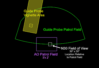
Figure 1: Schematic of the layout for LUCI-AO, including the automated guider and wavefront sensor (AGW) patrol field (guideprobe shadow), the LUCI FOV, and the AO Patrol field.
In order to use SOUL with LUCI, an AO Ref Star is needed and it must fall within the AO Patrol Field. Shown left is a schematic diagram of: the off-axis automated guider and wavefront sensor (AGW) – used to guide and send active optics corrections to the primary mirror, including the patrol field where valid guidestars may be selected; the LUCI field of view (FOV); and the AO patrol field where valid AO Ref Stars may be selected.
Below are Digitized Sky Survey (DSS) images from the Observing Tool which illustrate an On-axis (M34, left) and Off-Axis (NGC 6240, right) view of this setup.
Since the AO Patrol Field is rectangular, the LUCI N30 FOV is not centered within it, and changing the position agngle (PA) will change the region of sky where suitable stars may be found, a simple search within a fixed radius may not guarantee success. While this may add time to preparing your proposal, it allows PIs to confidently propose targets for LUCI AO observations.
This section primarily deals with selecting Off-axis AO Ref Stars (although the methodology is applicable to using the science target as the On-axis AO Ref Star).
The easiest method to verify either your science target (On-axis) is acceptable, or if there is a valid Off-axis AO Ref star is to use the Observing Tool to visualize this check.
- Download the Observing Tool (OT).
- Download the AO-ESM-ARGOS Template Library.
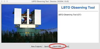
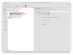
- Launch the OT and click Import XML. In the pop-up window navigate to where you downloaded the AO-ESM-ARGOS library file
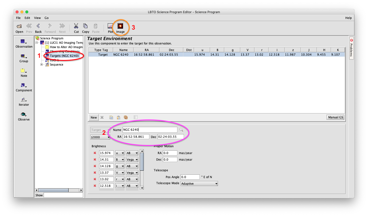
Figure 4: Science Program GUI with the Target Component selected. This shows the page used to enter the target name or coordinates and launch the Position Editor which will assist in visualizing the AO Ref Star in relation to the science target.
- Once you have selected the template to us, select the “Target” (#1 in Figure 4).
- Enter either the Target Name or R.A. and Dec. coodinated (#2 in Figure 4).
- Select the “Image” Icon (#3 in Figure 4) to launch the Postion Editor GUI Window.
Figure 5: Position Editor launched from the “Image” Button in the Science Program Editor GUI of the OT. Also shown overlaid is the AO Guide Star Selection Pop-up GUI which is used to select the type of star (AO Ref Star, Guidestar, etc) and which catalog to use. Shown is a DSS image of NGC 6240 (zoomed in) overlaid with the SOUL AO Patrol Field (purple box), the LUCI N30 FOV (white box), and the LUCI AGW Patrol Field (green angular lines). The orange-brown box should show the same Field of Views selected. This makes sure that the necessary fields are drawn in the Position Editor. The diamonds show stars which are valid for use as AO Ref Stars.
- Click the “Optical Image” button (#1 in Figure 5).
- Click the “GS Selection” button (#2 in Figure 5). This launches the smaller “Guide Star Selection” GUI window.
- From the two drop down menus in the “Guide Star Selection” GUI selet “LUCI AO” for Guide Star Type, and “UCAC5″ for Search Catalog (#3 in Figure 5). UCAC5 is preferred since it excludes galaxies previously included in stellar catalogs. If you wish to use your resolved target as the On-axis AO Ref Star – the catalog magnitudes returned may not be accurate. It is best for you to independently verify that the brightness of the target meets the requirements (e.g. measure the flux in a circular aperture of ~1”, use published values that match this method, etc.).
- As shown in Figure 5 a number of stars are highlighted with diamond symbols. These fit within a set of brightness parameters (9.8 < Rmag < 16.0) defined by the OT. Stars brighter than R~9.8 are still valid to use for Off-axis AO Ref Stars, however, they may saturate the LUCI detector (and will leave persistence as well as generate cross-talk noise across the detector) if their Kmag ≲ 12. The details of dealing with this are best left to Phase II script preparation once a proposal is awarded time.
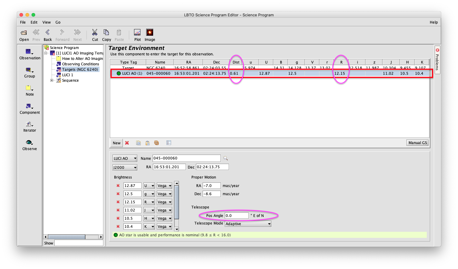
- Make sure to select the “LUCI AO” button on the left side of the Position Editor window (#4 in Figure 5). Next, click a star with a diamond around it to select it as the AO Ref Star to use. The selected star will appear in the Science Program GUI in the “Target” component. It will show either an R-band magnitude and the distance in arcminutes from the science target (see Figure 6). If the AO Ref star is the On-axis science target, it may show an r-sloan magnitude depending on what is returned from a SIMBAD or NED search.
Figure 6: Science Program GUI showing the target component with the science target and an AO Ref Star selected (highlighted by red box). Note that it shows the distance from the science target and the R-Bessel magnitude (purple circles). Also highlighted is the Position Angle selector.
In the example above, a number of valid stars were available at PA=0. In some cases, valid stars may not be within the patrol field unless a different PA is chosen. This can be done by adjusting the PA (highlighted in purple in Figure 6). This will rotate the N30 FOV, the AO Patrol Field, and the LUCI AGW Patrol Field together.
Once a viable star is found (or if the science target is found to be viable) the next step is to determine the expected performance. This is dependent upon brightness and distance from the science target (as well as expected seeing conditions).
If the only viable star(s) is (are) at the outer edge of the AO Patrol Field, Full AO may not be the best choice to improve the angular resolution. At such distances, one will not achieve diffraction limited performance (regardless of the brightness) and in fact could result in degradation of the image quality. In these cases, Enhanced Seeing Mode may be a better alternative.
Estimating the Actual WFS Magnitude
The R-Bessel or r-sloan magnitude for the AO Ref star is sent to the SOUL AO system to begin the process of closing the loop. The closer the catalog magnitude is to what the SOUL wavefront sensor (WFS) measures, the better the predicted AO corrections will match the real corrections (natural seeing conditions aside), and the more efficiently the AO loops will close.
The filter used by the SOUL WFS is not a R-band filter (typical 50% cuton/cutoff is 0.56μm ≲ R ≲ 0.72μm), but covers 0.6μm-0.82μm (LUCI-1) and 0.6μm-0.95μm (LUCI-2), where the cutoffs are defined by the LUCI dichroic entrance windows (see the LUCI pages). The WFS detector’s QE peaks between 0.65μm-0.75μm. Therefore, the UCAC or NOMAD R-band (or r-sloan) will not match 1:1 to what the WFS measures.
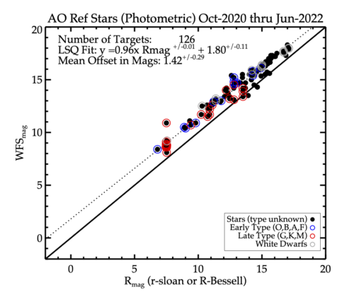
To estimate the actual WFS magnitude compared with the catalog R-magnitude, LBTO has been tracking all stars observed since Oct 2020. Below is comparison between the catalog and WFS mag values reported by the LUCI SX SOUL wavefront sensor through June 2022. The plotted points are data obtained during photometric conditions. The empirical fit does not change (within the errors) as a function of spectral type of the star. In previous comparisons, the offset has averaged 1.2 mags since October 2020.. The most recent comparison shows a somewhat larger offset, but an increase in the errors (1.42 +/- 0.29). This is still consistent with WFSMag = Rmag + 1.2. Thus, if one selects an AO Reference star of Rmag=16.5, the WFS will measure a mangnitude of ~ 17.7. In some cases, the difference between the Rmag and WFSmag will cause the SOUL WFS to readjust parameters. This will add overheads to the time to close the AO loop. In order to reduce this overhead, the Observing Tool now automatically adds an offset 1.2mag to the LUCI script. The Rmag sent to the SOUL WFS is a fainter value which should match what the WFS actually “sees” thus reducing overheads.
Estimating AO Corrections
To estimate the expected performance, Arcetri has put together a SOUL Strehl Calculator. This can be usd to estimate the performance of either the On- or Off-axis AO Ref star.

- Select WFS magnitude radio button
- Enter the estimated WFS magnitude (WFSMag = Rmag + 1.2)
- Enter the angular distance between the AO Ref star and science target (enter ‘0’ if the science target is also your AO Reference star).
- Enter your estimated seeing
- Enter the Zenith angle for your observations (input of 0 = overhead, 60 = 30 degree elevation limit).
- Enter the science wavelength in nanometers
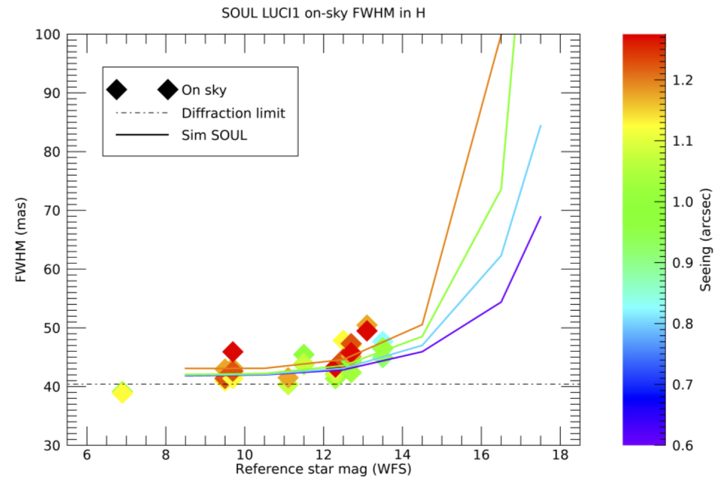
The Strehl calculator will return a predicted angular improvement. To convert to pixels, the N30 camera has a plate-scale of 0″.015/pixel. In addition, plotted below are empirical data from previous commissioning runs showing measured Strehl ratios vs. simulated results.
Figure 7: On-sky Strehl Ratio measurements at H-band with LUCI-1 plotted against the WFS magnitude. The data are color coded by measured seeing from the DIMM (diamond points). The lines represent simulated results. The data shown include results from commissioning work through end of 2020.
| Bin | Catalog Rmag range |
| 1 | Rmag < 11.5 |
| 2 | 11.51 < Rmag < 13.3 |
| 3 | 13.31 < Rmag < 15.2 |
| 4 | Rmag > 15.31 |
Diffraction Limited AO vs. ESM
Off-Axis AO Performance
For science cases which require the use of an Off-axis AO Ref Star, the distance between it and the science target has a significant impact on the corrections which can be achieved. Shown below are simulations at J- and K-band for various AO Ref stars as a function of distance from the science target, and the expected angular resolution.

Figure 9: Predicted angular resolution achieved for science targets as a function of four AO Ref stars of different brightness and their increasing distance from the science target. Top planet shows K-band, bottom shows J-band. These are compared with the diffraction limit of the telescope. Recall the AO Patrol Field is 3’x2′.
As shown in Figure 9, as the distance between the science target and AO Ref Star increases, the angular resolution degrades. Although the AO Patrol Field is 3’x2′ in size, as the science target and AO Ref star become further separated, the shape of the PSF begins to elongate in addition to reduced angular resolution.
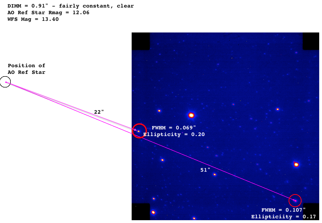
Shown below is an example of a 60 second Ks-band image where the AO Ref Star is ~20″ to the left of the N30 FOV. The FWHM of two bright stars are shown at opposite ends of the N30 FOV. The example demonstrates the impact to image quality as a function of distance.
Figure 10: LUCI-1 AO Commissioning data obtained in October 2020. The AO Ref Star is ~20″ away from the field. FWHMs (assuming a MOFFAT profile) are fit to two stars at the edges of the LUCI-1 N30 FOV (along with a measurement of the ellipticity). The data were taken in sub-arcsecond natural seeing (as measured by the DIMM) and the catalog and measured magnitudes of the AO Ref Star are shown. The stars in the field show elongation. The black boxes in the LUCI-1 N30 FOV are tabs (~3″ on a side) which house alignment pinholes.
Enhanced Seeing Mode as an Alternative Choice
As shown in Figures 9 and 10, as the distance between the AO Ref Star and science target increases, the angular improvements decrease. In addition, this can negatively impact the PSF, producing elongated shapes. This is because the higher order corrections which are computed for the AO Ref Star are for a patch of sky that may have different turbulence and characteristics than the patch of sky for the science target. In this case, and if the science target’s size ≈ N30 FOV, it may be more useful to use Enhanced Seeing Mode (ESM) rather than full AO. ESM provides 11 modes of corrections and is used with the N375 camera which has a FOV ∼ 4’x4′. The AO Patrol Field is within this field of view. In optimal conditions, corrections have achieved a FWHM ∼ 0″.22. The plate-scale of the N375 camera is 0″.1178/pix (LUCI-1) and 0″.1199/pix (LUCI-2). Recall that the N30 camera has a 0″.015/pix plate-scale.
Future work will include mapping out the point at which Full AO and ESM cross-over in the corrections delivered.
Calculating the Total Time Needed for Observations
Determining Exposure Times
The LUCI Exposure Time Calculator can be used to estimate the time needed to achieve a desired Signal-to-Noise (S/N) or estimate the S/N achieved in a specific amount of time.
The LUCI ETC does include the option to add a Strehl Ratio if the “Diffraction-limited mode” is selected for the “Telescope Modes” at the top of the page. Please use the Strehl Ratio output from the Arcetri Strehl Ratio Calculator.
When calculating the total exposure time needed there are a few caveats to keep in mind with LUCI+AO.
- Individidual exposures, either 1 NDIT or multiple NDITs in Integrated mode, should avoid exposure times (DIT) > 60-70 seconds. This is to avoid smearing from the limitations of passive flexure control. Passive flexure attempts to compensate for gravity forces on the instrument using a lookup table which is interpolated based on elevation of the telescope and instrument rotator angle. This will add overheads to the total time for observations.
- It may be more prudent to save NDITSs in a Cube rather than Integrated mode (which takes all the NDITs and combines them into a single exposure). This can help avoid the issue of smearing from passive flexure, however, each NDIT saved to a Cube adds 0.2 seconds of overhead. This also has the added advantage that if the AO loop opens for a short period of time, most of the frames can still be recovered.
- In order to reach the background limited regime the minimum exposure times needed for the broad-band filters are (using LIR mode – see the LUCI Detector page for more information):
- J > 35 seconds
- H > 8 seconds
- K > 6 seconds
- Ks > 11 seconds
- Each DIT is read out and resets the detector, therefore reaching the background limited regime is “reset” each time a DIT is read out. Stacking DITs is not a cumulative way to reach the background limited regime.
- For the z-, medium-, and narrow-band filters, use the MER mode (see the LUCI Detector page for more information). The minimum integration times needed to reach the background limited regime is 60 seconds.
- In some cases, the brightness of the target and/or science will require exposure times < minimum time to reach the background limited case. These exposures will be readnoise limited. S/N calculations and analysis of the data should take that into account.
Overheads for LUCI and AO
The LUCI SciOps Instrument pages contains an Overhead Page with a table that should be referenced when determining the total time needed for LUCI-AO observations. Currently, on average, the AO preset can be completed (loops closed and control returned to LUCI) in 10 minutes. If the AO Ref Star magnitude is significantly different than the magnitude computed by the SOUL WFS, the overhead can be as high as 20 minutes.
Additional Information for Planning
Angular Differential Imaging
Sub-frame readout
In some cases, the science target may be too bright for the LUCI detector, causing saturation of the signal (this would be seen as a pedestal in a plot of the object, either 2D or 3D isometric view). To check if your targets may be saturated using full-frame readout, use the LUCI ETC , enter the magitude of the target and filter desired, and enter 2.51 seconds for the Detector Integration Time (DIT) box at the bottom of the page. If this returns as ‘saturated” on the S/N results page, you may need to use sub-frame readouts. This reads out a portion of the LUCI detector. The advantage of this is that the readout size scales inversely with the minimum detector time (2.51 seconds). This mode is not officially released yet for use, so please contact sciops@lbto.org if you think your program may require sub-frame readouts.
PSF Stars
In many cases, it is a good idea to observe a star of similar magnitude and color to your AO Reference star (even if the target itself is the On-axis AO Reference star). This allows for use of deconvolution to remove the signal of the point-spread function (PSF) and extract faint features. Examples of this scenario include observing a bright QSO on-axis, or a resolved target with an Off-axis AO reference star.
In the case of Off-axis AO Reference stars, one should observe a pair of stars with the same separation and PA as the science target and its AO Reference star. The star used for the PSF deconvolution will not be the AO Reference star in the pair. The goal is to obtain a PSF with the same shape, which is affected by a targets distance from the AO Reference star. ESO has a useful webpage for finding stellar pairs based on brightness, color, separation, and PA. For completeness one should estimate the time needed to observe the PSF star and include it as part of the overheads when requesting time for LUCI-AO observations.
Moon Limitations
Although LUCI-AO observations are in the near-IR and are less affected by the Moon, the SOUL WFS camera operates between at 0.6μm-0.82μm (or 0.95μm). One may wish to consider these issues both in requesting time, and in Phase II planning. Keep the anglar distance from the Moon ≳ 15 degrees for all observations.

