Real-Time Display
RTD User Interface
The Real-Time Display (RTD) is the primary interface used for quickly viewing data in real time, and performing Long slit and MOS alignment. It is opened from the Observation GUI by clicking the RTD1/2 button below the corresponding status panel on the LUCI observation execution panel and the RTD control GUI will pop up. As with the other GUI’s, to help distinguish the LUCI1 RTD User Interface is periwinkle and the LUCI2 RTD UI is pink. The control buttons on top are used to start/stop the Aladin display server and reset the RTD input parameters.

At the base of the RTD are 3 connection status indicators that will be green when the RTD is connected to an open/started Aladin session, loaded bad pixel map is active, and the RTD is connected to the LMS database containing mask files.
The RTD User Interface consist of 5 tabs: Live View, MOS, Long Slit, Sub Windowing, AFC. These tabs guide users through examination of data and alignment.Sub Windowing is not a released mode and is only available for engineering at this time.
LiveView
Users can easily recall archived data for comparison, perform image subtractions, and load bad pixel maps. The most recently saved image will automatically be displayed in Aladin. With this tab, one can then subtract background/sky or dark frame as needed, load previous images for comparison purposes, etc.

Up to 10 images are displayed of each of the LiveView image dropdown lists. Users can add additional images with the Add button, which opens a popup allowing users to access local archived images.
MOS
Multiple reference stars are used to correct the translation and rotation of the mask and sky on the detector so that the multiple science targets will all be well-aligned in their slitlets. It takes the sky, source, and through-slit images as input. This tab is used to perform MOS acquisitions. Once the sky, source, and thru slit images have completed, confirm the file names have auto populated correctly in the Mask Alignment and Target Alignment sections of the MOS Tab. The LMS mask file associated with each observation is automatically loaded into the RTD from the local database.
The MOS RTD tab is broken in to 2 sections: Mask Alignment and Target Alignment
Mask Alignment
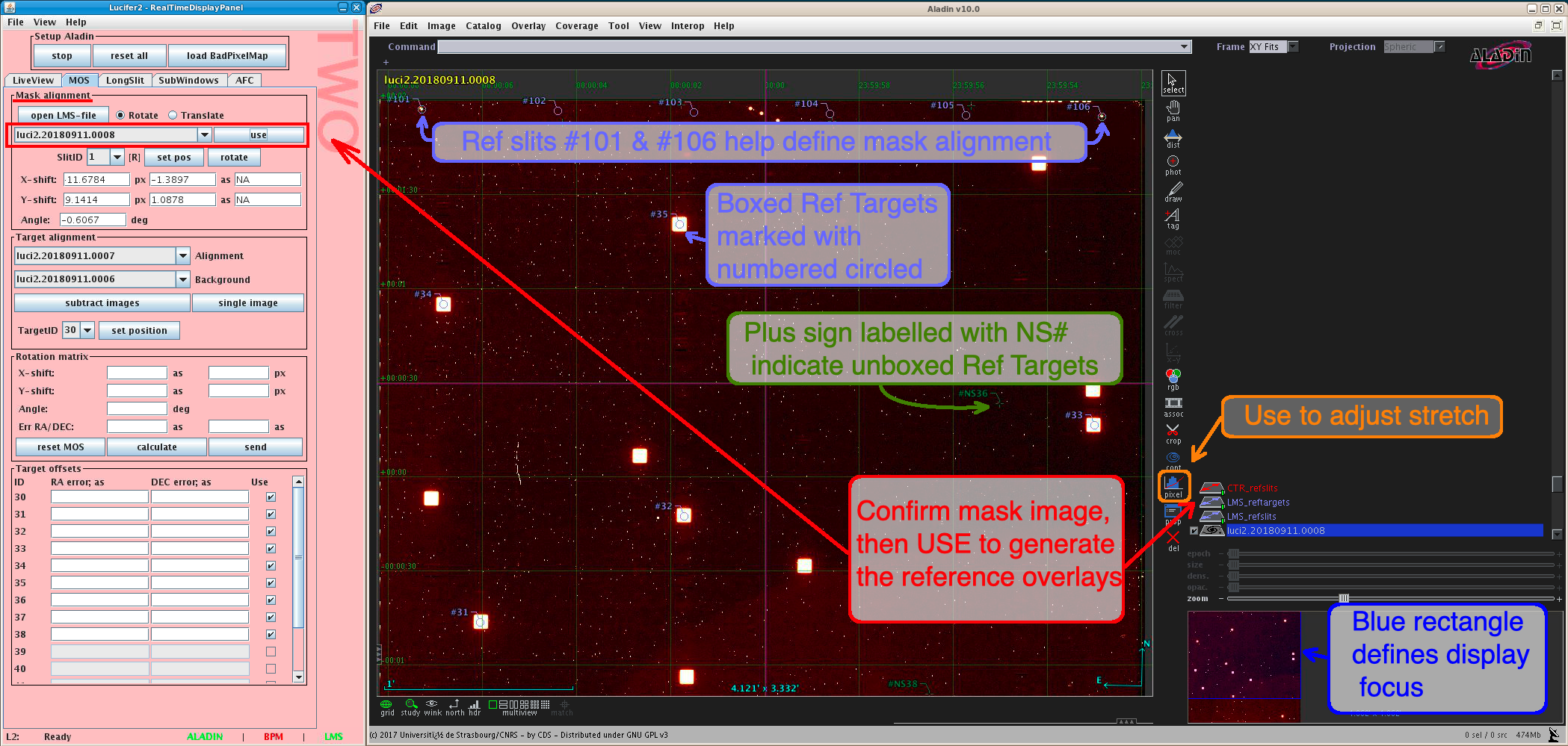
Once the Mask image is confirmed and populated into the Mask Alignment part of the MOS tab, start the Mask Alignment by selecting USE. This will generate several overlays in the Aladin display:
- LMS refslits: Used in the Mask Alignment. These highlight the reference holes along the top of the mask #101-106.
- LMS reftargets: Used for the Target Alignment. There are 2 types of RefTargets: Boxed and Unboxed. The boxed alignment sources are labeled with a periwinkle label, while unboxed sources will have a dark green marker. The label numbers 30-39 will match those of your alignment sources in the LMS file.
Check the alignment of the LMS refslits. The alignment of #101 (top left) and #106 (top right) are all that are needed for Mask alignment. If the overlay matches the physical mask holes then no action is needed and you can move on to the target alignment, align the refslit:
- select the SlitID from the drop down menu
- Click on the slit that corresponds to the SlitID and hit “Set Pos”
- you should see the LMS refslits overlap update. Check the slit on the other slide. If ok, move on, otherwise repeat with opposite side slitID.

Target Alignment
Once the mask is aligned, align the Alignment source.
- Confirm that the Background and Alignment image have populated into the appropriate places in the Target Alignment portion of the MOS tab. If no background image taken select “Single Image” otherwise “Subtract Images”. A subtracted image will appear in Aladin with the LMS reftargets overlay. The RTD will calculate the translation and rotation necessary to optimize alignment on the sources.
- An initial calculations will be determined using all sources. Zoom in on several sources and make sure the overlay is accurately predicting the source position relative to the actual image position. If not, select the alignment source number from the dropdown and click on that reference source in the image. “Set Position” to centroid on the updated source position.
- The calculated translation and rotation offsets for the provided alignment sources is provided along with the associated residuals. In the “target offsets” section at the bottom of the MOS tab on the RTD, check if any of the alignment sources have large residuals. If one source has particularly large residual, you may wish to deselect this one source as it is possible that the astrometry on this source is bad. Recalculate and check residuals. A minimum of 3 alignment sources are required and these should be well distributed for an accurate solution.
- Once confirmed that the offsets make sense (the residuals are not too large), then hit Send to the offsets to the Observer Panel. The offsets will appear as new observation elements.
- Hit GO to execute. A confirmation thru-slit image is taken.
- If happy with the alignment source in the boxes and slits, click GO again to start executing the spectroscopic portion of the script. If not, you may manually execute a small offset on the Telescope Service GUI and take another image to confirm your source position in the slit. Manually take the other image using the RMGUI.
Long Slit
The Long slit alignment corrects for the source position with XY offsets. A second source can be used in the calculation to correct for rotation. Just as with the MOS offset calculations, 2-3 images are required as input: Sky (optional), Source, and Thru-Slit Image.

The Long-slit tab is comprised of 3 sections that guide the user through the slit alignment: Target Selection, Slit Selection, and Long Slit Result.
Target Selection
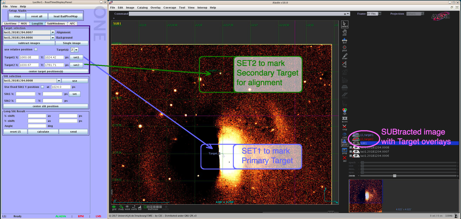
- Confirm that the Background and Alignment image have populated into their respective fields. If no background necessary (Tellurics or bright sources) select Single Image. Otherwise select Subtract Images to subtract the background from the alignment image.
- Select number of targets to align from the dropdown: 1 or 2. Alignment of 1 target will perform a translation correction only. 2 targets along a slit will correct for translation and rotation.
- Click on the center of the primary source in the Aladin window and select SET1.
- “Center Target Positions(s)” can be used to centroid on the core, but keep in mind that this function will center on both sources simultaneously if aligning on 2 sources. Check the centering after using this function.
- If centering on 2 sources, click on the center of the second source and click SET2.
- Repeat until satisfied fiducial is centered accurately on the source.

Slit Selection
- Confirm the slit image has populated into the slit image field of the tab. Select “Use”. This will bring up the slit image in the Aladin field. You will also see and overlay indicating the position of your target(s)

- Click in the Aladin display on the slit image where you would like to place your primary target (Target1). Users can fix the initial y position of Target1 at pixel 1024 by selecting the radio button, or users can select the optimal y position for their project. Optimizing the stretch will help to determine the best centering in the slit. Select SET once in position.
- Users can use the “Center Slit Position” to optimize the slit position. NOTE: Slit centering optimization was updated in 2019B and is recommended.
- The Second Target/Slit will automatically center once the primary target/slit is centered. Visually confirm.

Long Slit Results
- Calculate. Confirm the calculated shifts and angle seem reasonable. If you are seeing large offsets or large angles there could be an issue with the target or field. Confirm the targets and field with a finder chart.
- Once confirmed that the offsets make sense, then hit Send to the offsets to the Observer Panel. The offsets will appear as new observation elements.
- Hit GO to execute. A confirmation thru-slit image is taken.
- If happy with the alignment source in the boxes and slits, click GO again to start executing the spectroscopic portion of the script. If not, you may manually execute a small offset on the Telescope Service GUI and take another image to confirm your source position in the slit. Manually take the other image using the RMGUI.
Subwindow Readouts

The LUCI detector can be partially read out in order to reduce the minimum DIT, useful for when you have a source of interest that saturates in the minimum detector integration time (DIT). However the reduction is only linear in X [DITmin = 2.53 * (Xsubwindow / 2048) ] because of the layout of the 32 amplifier channels on the detector. There is no time savings in reading out less than the full 2048 pixels in Y, though the file sizes would be smaller. Keep in mind the full detector is still illuminated as before, sub windowing has no effect on that.
Subwindow control is done on the RTD’s SubWindow action tab. It is best to always start with a full-frame image displayed in the Aladin GUI. To set a sub window click in the image where you want the sub window centered, then click “Get Coords” in the RTD. Select the size of the desired sub window from the drop-down lists (Y is normally left at 2048) and the click “Draw Subwin” to see where the sub window will be placed on the Aladin GUI. Click “Set sub window” in order to actually implement the sub window readout. If you then go to the readout manager (RMGUI) and ask for a 0.0s exposure it will default to the new minimum DIT for that configuration. It is always best to read out an image manually to ensure the sub window is correctly set before continuing with any scripted observation.
You can click “reset form” at any point before the sub window is set to go back to defaults and start over. Once you have a sub window set you need to click “Reset to Full Frame” in order to clear out the sub window. As above, it is best to read out an image manually to ensure the sub window mode has been correctly cleared and you are back to full frame readouts.
AFC Tab
Although AFC (Active Flexure Compensation) is still in the commissioning phases and is not currently available for science, this tab contains features that are useful for daily science uses.
The Field Stop can be realigned on the N3.75 images or N30 camera images using the AFC tab. Do not try to align on the N1.8 camera images!
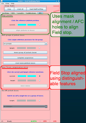
There are 2 methods for adjusting the Field Stop with the AFC tab: “Align Pinholes to Boxes” & “Move Flexure Compensation Mirror”. NOTE: If move is ~10% of the field or greater, call an ISA for support.
Move Flexure Compensation Mirror
“Move flexure compensation mirror” section can be used to adjust the flexure fold mirrors to align the field stop using identifying feature in the images
-
- In the Aladin Window, click on a distinguishable spot on the image (see where “current” is noted – it can also be a corner). Then select the “Target” radio button.
- In the Aladin Window, select to where you want the current spot to move. For examples, a feature at the center of a mask will want to move to pixel (1024, 1024).


- Once confident with the pixel positions of Current to Target, select the “Move Mirror” button to move the mirror. A pop-up window will ask you to confirm you want to do this move. Wait 20 seconds (this is to make sure the motors move – you can also verify by looking in the message log located in the Observer GUI below the “LOAD” “GO” “Reset” “refresh” “Locate” and “Other” buttons.
- Take a second image to confirm the move was applied. Repeat if needed.
Align Pinholes to Boxes
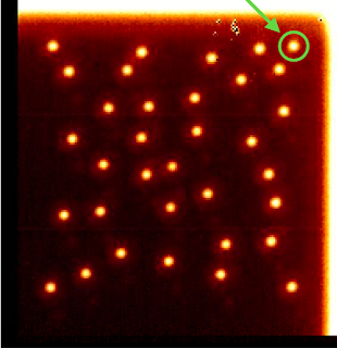
One can use the Align Pinholes to Boxes for several facility masks such as the N30 Field Stop and updated masks containing AFC holes such as the LS_0.25arcsecond mask. These masks have pinhole designs that can be used to help with alignment. When the appropriate mask is in the FPU, a set of white boxes will be overlaid on the mask image to show the default location of the pinholes (i.e. where they are supposed to be located). The mask must be in the FPU at time of alignment for the overlay to be visible and this method possible.
In the case of the N30 Field stop, select the pinhole in any corner tab closest to the mask center (see image below for the bottom left corner), then click OK when asked if you are sure.
For Long Slit masks with AFC masks, select the top right AFC hole in either the top or bottom pattern and click ok when you are sure. Wait 20 seconds (this is to make sure the motors move – you can also verify by looking in the message log located in the Observer GUI). Take another image to confirm the alignment. Repeat if necessary
| N30 example: | AFC Long Slit Example: |
 |
 |