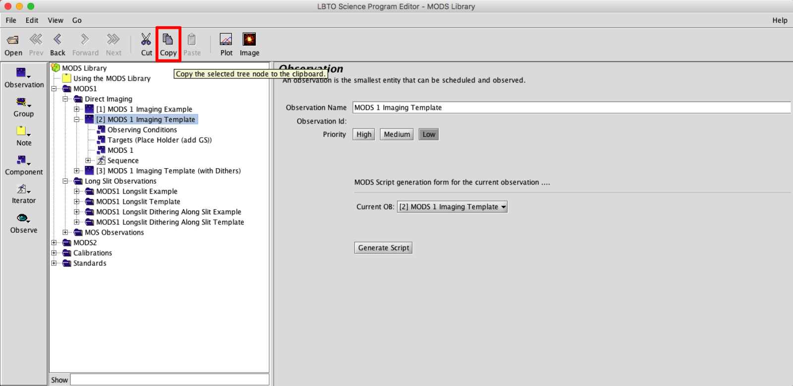
1: Imaging Example
Example 1: Setting up Direct Imaging Observations
Highlight the Imaging Template and then click COPY in the Main Toolbar.
Back in the *empty* Science Program PASTE the observations by clicking PASTE in the Main Toolbar
Tailor the Template with your observation details by clicking on the Observation Template in your Science Program Tree and filling in each element (Observing Conditions, Target, MODS, Sequence, etc.) as detailed below:
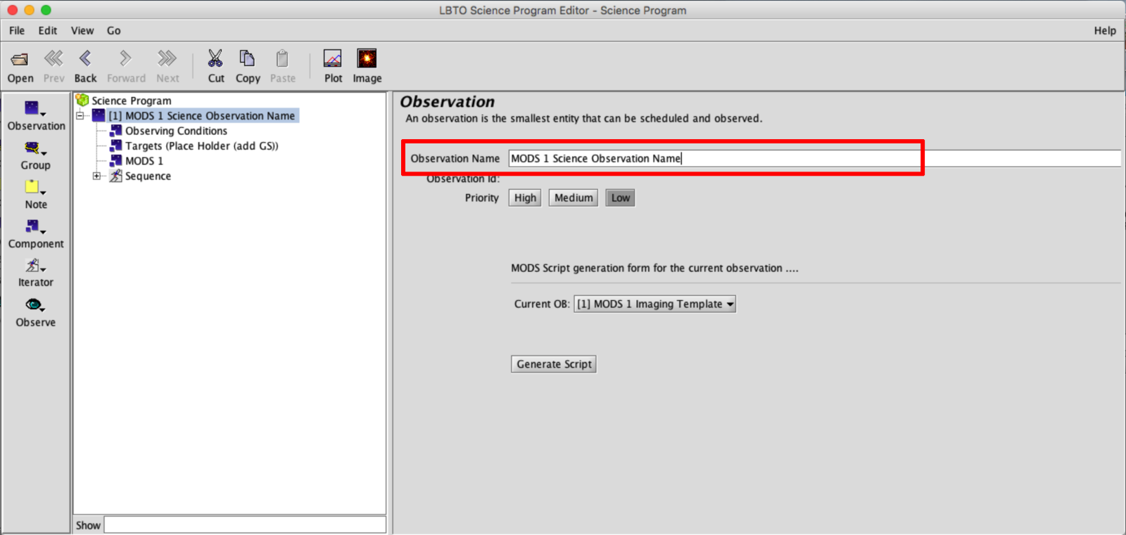
- Observation Element: Change the Observation Name from the generic template name to something descriptive. This can help observers easily identify observations in the OT Science Program if multiple observations are provided.
- Observing Condition Element: Complete the information in the Observation Conditions Element by selecting the nodes that roughly align with what was requested in your proposal. These conditions are not currently guaranteed and are not passed to the script in any way, but may be a helpful reminder.
Pro Tip 2: Since Observing conditions information is not passed along in the Observing Scripts, it is important to not only pass along your complete scripts but this complete OT Program as well to LBTO and the Partner Coordinator. Details for exporting the OT are available here.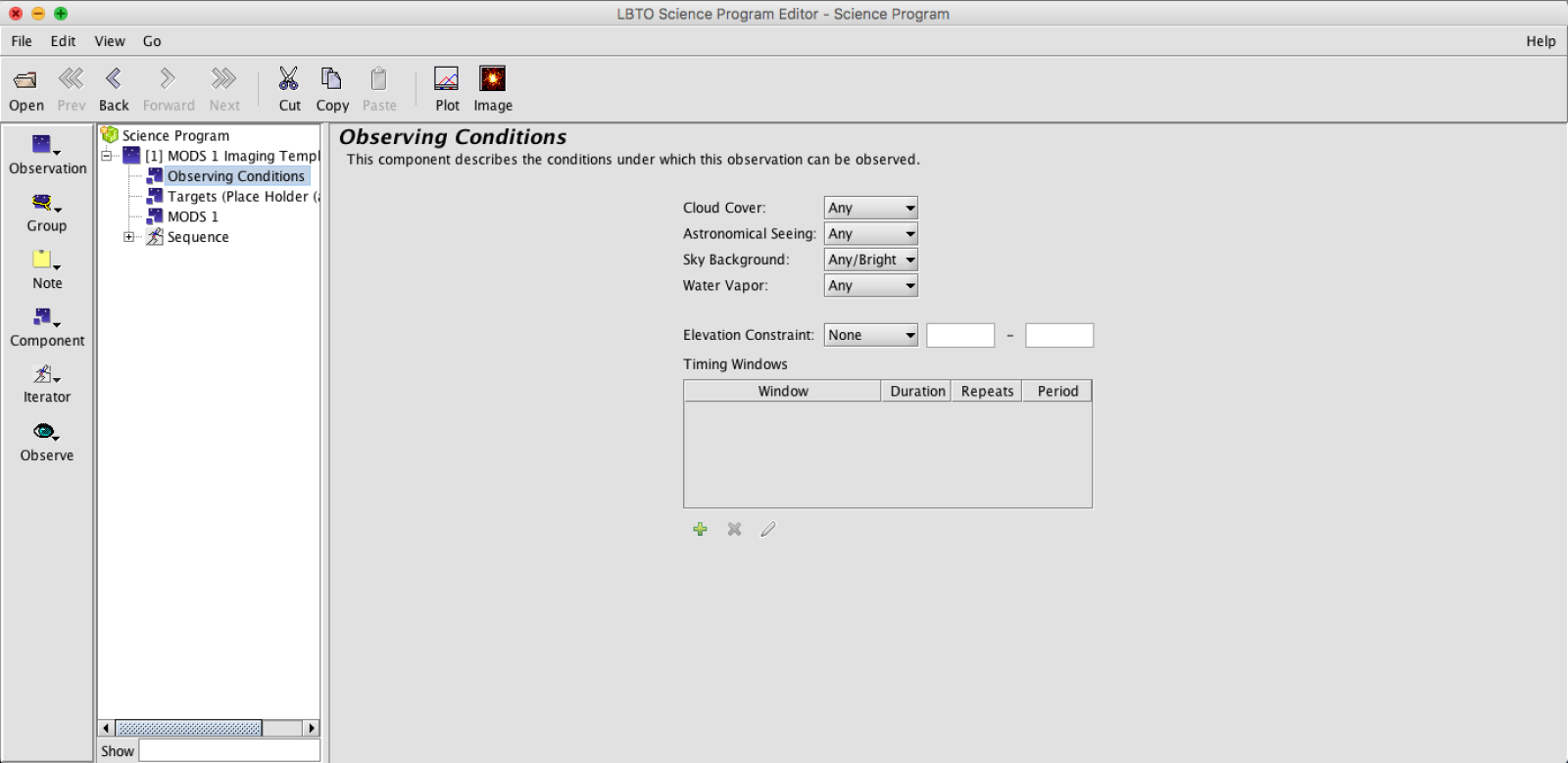
- Target Element: Enter Target. Either enter a valid SIMBAD Target Name and hit enter. If recognized, the coordinate field, magnitudes, and proper motion will populate. Or manually type in your Target Name, Coordinates, Brightnesses, and Proper Motion. In this Element you can adjust the Position Angle of the observation (circled in green below).
 Click on the Image button in the Main Toolbar to bring up the Position Editor. The Position Editor will allow you to visualize the Target, as well as the the Guide Patrol Field and Mask (not needed for imaging). The Position Editor can be used to visualize and select a guide star. Details about guide star selection can be found here. Offset patterns will also be overlaid. To bring up a default Catalog Image in the Position Editor, click on Image in the Toolbar in the Position Editor.
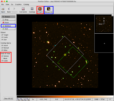 Select the desired elements in Field of View area to see overlays of the Guide Probe FOV, Science FOV and Masks (these often will come up by default).
 - Obtain a Guide Star. This can be done in one of two ways.
- Target Element: Select New in the Target Element. In the drop down menu, select MODSGS to create a new guide star element in the Target Environment. You will need to manually enter a valid SIMBAD designation or the RA/DEC for the Guide star. This is a useful option is the guide star is previously known.

- Position Editor: Click the “Manual GS” button on the right of the Target Element. This will bring up the Position Element with a popup. In the popup you can select either the NOMAD or UCAC4 catalog for your Guide Star options.
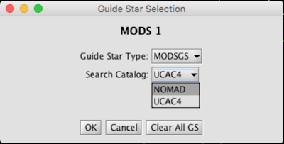
Once you select OK, the catalog will be queried and the catalog stars will be highlighted in the Position Editor (green circles for NOMAD and turquoise boxes for UCAC4). Select the +MODSGS option on the Left Sidebar then click on guide stars that fall within your Guide Probe FOV (overlay outline green). If you choose a valid guide star, you will see a yellow overlay of the actual probe footprint appear over the selected guide stars. This will allow you to see if the probe will vignette. The selected stars will also populate the table in the Target Element.
- Target Element: Select New in the Target Element. In the drop down menu, select MODSGS to create a new guide star element in the Target Environment. You will need to manually enter a valid SIMBAD designation or the RA/DEC for the Guide star. This is a useful option is the guide star is previously known.
- MODS Instrument Element: This element defines the initial configuration of the instrument. Set the Configuration first: Dual Imaging, Red Imaging, or Blue Imaging. If observing a particularly bright guide star, one may wish to insert a filter into the AGW. In the Camera element(s) select the filter, exposure time, number of exposures, and binning for the initial instrument configuration filling in the fields and nodes (not that for imaging the CCDReadout is defaulted to 3Kx3K).
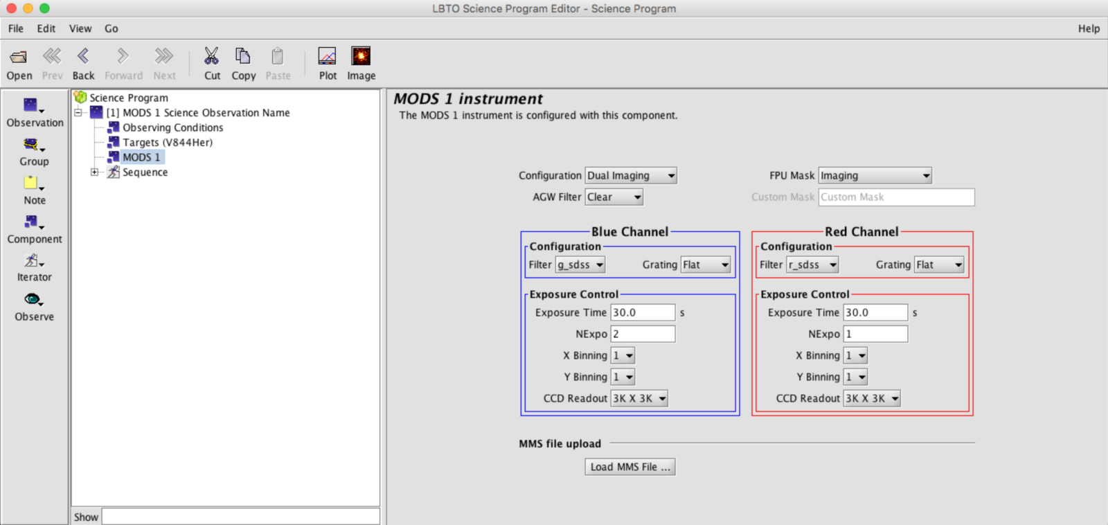
These can be adjusted for exposures beyond the first exposure in the sequence tab. - Sequence Element: The MODS Imaging Sequence is composed of 2 to 3 components: MODS Sequence Iterator, possibly an MODS Offset Iterator, and Observe Type. With MODS, Offsets are not often performed so the Offset Iterator may not be present. Many templates do not contain an offset iterator, although the instructions below describe how to insert offsets.
-
- Edit MODS Sequence Iterator:
 Edit the sequence of filters, exposure times and number of exposures. The item values default to those set in the MODS Instrument Element if not changed in the Sequence Iterator. For example, if the number of red exposures (Red Nexpo) is set to 4 in the MODS Instrument Element, it will be set to 4 for all filter and exposure time combinations unless explicitly changed, even if the number of exposure item is not made visible in the Instrument configuration.
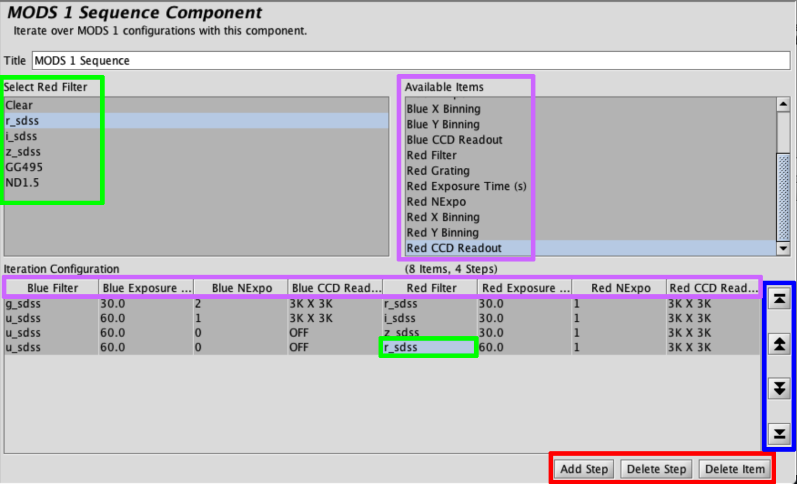
The Delete Step button can be used to remove any lines in the existing Iteration Configuration, and the Add Step button can add a new line to the Iteration Configuration. Clicking on items in the Available Items section will allow the user to alter that item in the Iteration Configuration (either highlighting that item in the Iteration Configuration or making it visible if not already), opening a menu or field to the left of that Available Items section. Details can be found at MODS Sequence Iterator. - Add/Edit MODS Offset Iterator: To include a dither pattern, add the MODS Offset Iterator to the Sequence by clicking the Iterator Button in the Left ToolBar and selecting MODS Offset from the menu.
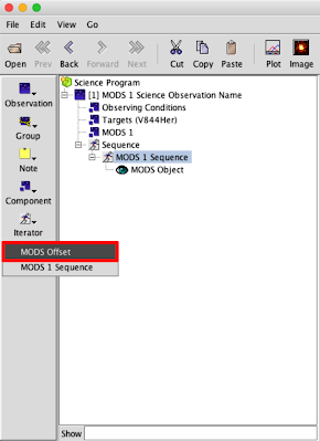
The MODS Offset iterator will appear.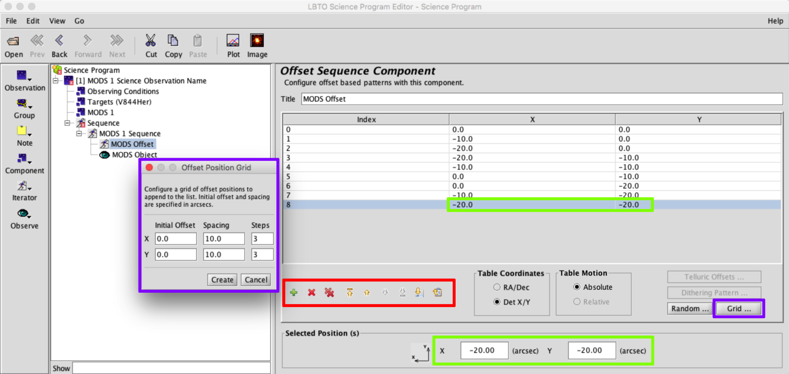 Use the Iterator Action Items (in red box above) to add, remove, or move offset positions. Add dither patterns using the Pattern Generators,such as the Offset Position Grid shown above (purple). Offsets can be adjusted by selecting the desired offset in the table, then entering the new value in the Selected Position(s) field at the bottom (green). By selecting the elements in the Sequence and dragging them, the order of the sequence can be adjusted. Rearrange the order of the Iterators in the sequence depending if you want to cycle through each filter at each dither position before moving to the next, or complete the full dither pattern in a particular filter combination before changing filters and repeating the dither pattern. The last item in the sequence must always be the Observe Type. For example:
- Observe Type: For Science Observations this will always be set to MODS Object, Class Science. For Standard Stars you should change the Class to Standard.

- Edit MODS Sequence Iterator:
- Review and Generate Script: Once the above has been complete, the Sequence Element can be used to review Instrument and Telescope changes.
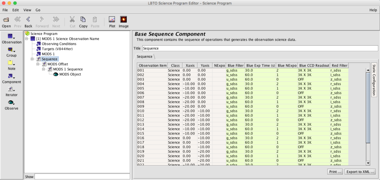
Instructions for generating a script from the observation are available here.

