LUCI Offset Iterator
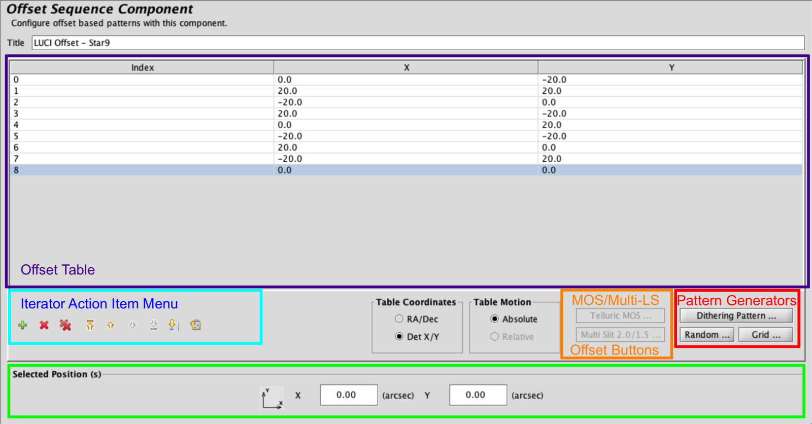
The LUCI Offset Iterator allows users to specify dithering patterns in the Absolute Det X/Y coordinate system. The iterator consists of: a Top Frame, called the Offset Table, where X/Y offsets appear in the order of execution next to an assigned index, an Iterator Action Item Menu, with buttons that control the addition, subtraction and order of entries in the table and allows for upload and download of dither patterns, Pattern Generators, which contain common dither patterns, random and grid offset generators, and a bottom Position Frame with text boxes for editing or inputting offset values by hand.
Iterator Action Item Menu
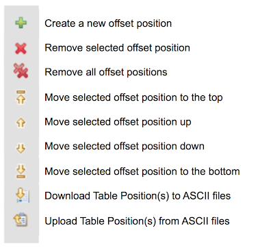
Most of the buttons in this menu are self explanatory, simply adding, removing, or moving items in the Offset Table to change the overall sequence. However, the Upload and Download buttons at the far right of the menu are of interest. The Download Table Position button is a useful way to save complex dither patterns. Once depressed, the button will bring up a dialog box requesting the user save an ascii file to their local hard drive.
If you would like to use this downloaded dither pattern in another program or for an observation in the same program, you can use the Upload Table Position to ingest the file and convert it into values on the Offset Table . You may also upload homemade offset files; be sure they are ascii files that conform to the correct file format. An example is here.
Pattern Generator
There are three pattern generator tools in the offset iterator, the random generator, the grid generator, and the Dithering Pattern Generator. Since the goal of dithering with LUCI is to carefully construct a sky frame that has sky on every pixel, we recommend using one of our pre-generated dither patterns which are available in the Dithering Pattern button or the random generator.
The user may input a scale factor (in arcseconds) that will apply to the pattern they have selected. If the user does not want to choose a scale size themselves, the tool will insert a default value, which is recommended in most cases. If the user would like to set their own scale, they may type in values in the Scale dialog box.
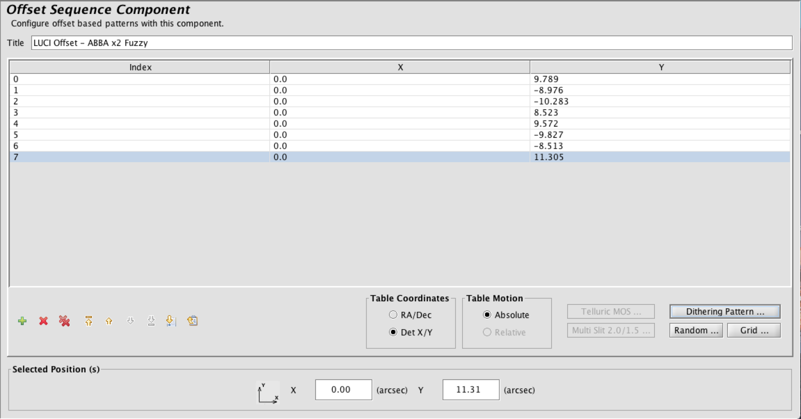
If the user would like to repeat the pattern, he or she may click on N Repeats and enter a new value; so a ABBA pattern with N Repeats = 2 would yield 8 positions. Once the value of N Repeats is great than 1, the Fuzzy button to the text box’s right will activate. Selecting Fuzzy will add a slight random offset to all the values created by the tool, to ensure that no position is exactly repeated.
- Img Pair: Two positions. Relative DetXY. Excellent for Spectroscopic Acquisition
- Dice 5: Absolute DetXY for Imaging
- Star 9: Absolute DetXY for Imaging
- AB: Two Y-only offsets. Dither along slit. Absolute DetXY
- ABBA: Four Y-only offsets. Dither along slit. Absolute DetXY
- ACBD: Four Y-only offsets. Dither along slit. Absolute DetXY
Multi-Slit Offsets
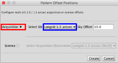
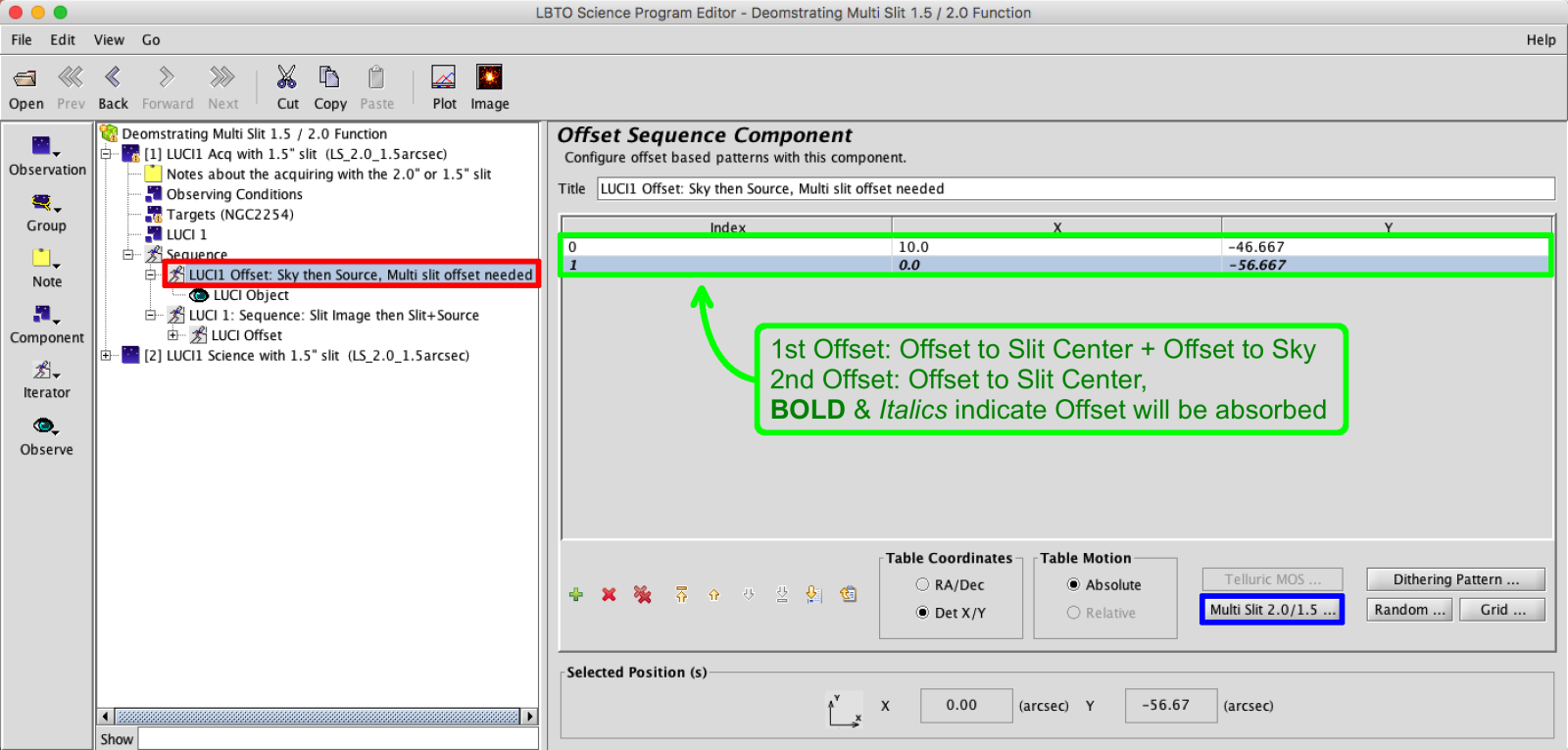
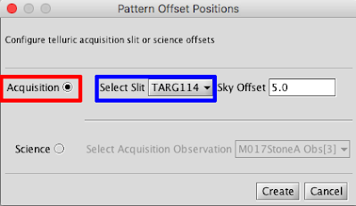
The user would select the appropriate slit from the drop down menu. This would define the necessary offset to the desired slit center (-56.66 arcseconds in Y to the 1.5″ Longslit center and +56.66 arcseconds in Y to the 2.0″ Longslit center). There is also a section for the offset to sky. The default of 10 arcseconds is acceptable for most cases. This will apply an offset of (+10, +10) for the Sky image.
The BOLD and Italicized offset will be Absorbed by the telescope offset. Absorb is a command that will redefine the pointing origin as the current location. This means that all absolute offsets will now take place from this newly defined Pointing Origin. The absorb will always take place after the offset.
Once the offset is absorbed, there is no need to apply it in the other sequences in the acquisition.
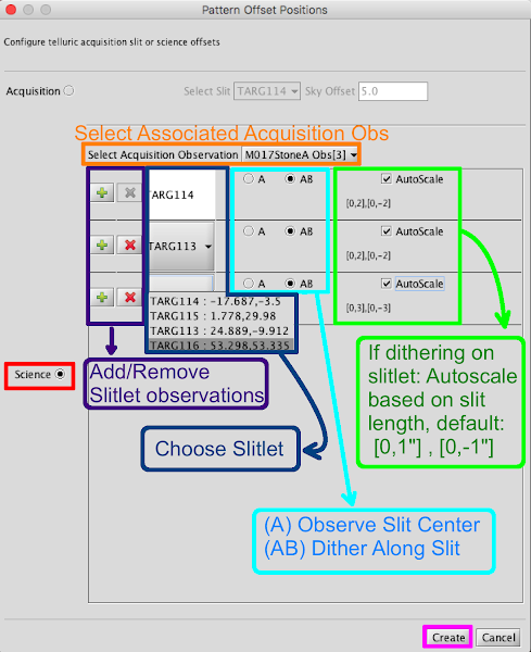
For the Science observations, select the Science radio button. And rather than selecting the slit, the user will select the associated Acquisition Observation.
The generated offset will appear as a greyed out Italicized offset matching the offset to the center of the slit from your Acquisition. The light grey indicates a place holder, and not a physical offset. Note this offset will not appear in your Sequence. Once this has been placed in the Offset Iterator, the user can build a dither pattern for the science target as normal. The dither pattern will accurately display in the Position Editor.
MOS Telluric Slitlet Offsets
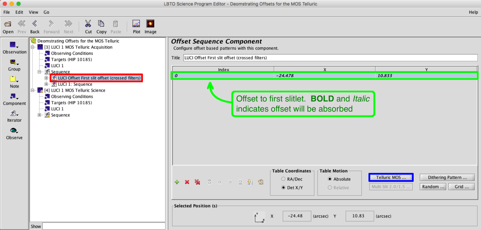
MOS Tellurics require offsets to place the Telluric star in particular slitlets. The MOS Telluric Acquisition places the telluric star in the first slitlet, typically a nearest corner. During the science the star will be offset to several slits, and possibly dithered along those slitlets. The offset option will only become available if, in the Instrument Element, a custom mask is selected, and if “Yes” is selected in the Telluric dropdown menu.
The user will need to select the desired initial slitlet from the drop down menu. The TARG names match those in the mask LMS file. There is also a section for the offset to sky. A Telluric Observation does not take a “Sky” image. The Telluric is bright so no sky subtraction is need for the alignment procedure. The default of 5 arcseconds is acceptable for most cases. This will apply an offset of (+5″, +5″) for the Source image. This number can be adjusted as needed.
As with the Multi Slit Acquisition, the BOLD and Italicized offset will be Absorbed by the telescope offset. The Absorb is a command that will redefine the pointing origin as the current location. This means that all absolute offsets will now take place from this newly defined Pointing Origin. The absorb will always take place after the offset.
Once the offset is absorbed, there is no need to apply it in the other sequences in the acquisition.
For the Science Observation Select the “Science” Radio Button. Make sure the Acquisition Observation is selected up at the top. The first slit will auto populate with the slit selected in the acquisition. When the Offsets are created, this first slitlet offset will appear in light grey and italicized. As with the multi-slit offsets, the light grey indicates a place holder, and not a physical offset. This offset will not appear in the sequence or script, but ensures the visualization is accurate. If an AB dither was selected (third column) this dither will follow. The user can add slitlets with the “+” button.

