PE Left Sidebar
The Position Editor Sidebar can be broken down into 3 sections: Mode, Add, and View Buttons.
Modes
There are 3 different Modes:
Depending on which of these Mode buttons is depressed, interaction in the Position Editor viewer is different.
![]()
With this mode the user can move the cursor over the position editor viewer freely, without risk of dragging or erasing objects in the viewer (safe viewing mode). The user can view the coordinates in the lower bar of the position editor viewer. The normal cursor shape is unchanged (usually an arrow). This will be the default mode the position editor comes up in.
![]()
With this mode the user can modify target coordinates and orientation. The cursor is hand-shaped when in this mode and positioned over an object that can be dragged. The cursor shape is a pointer finger. This pointer finder can grab and manipulate specific handles. For example:
The new positions will be reflected in the Target Element of the Science Observation. The user can view the coordinates in the lower bar of the position editor viewer. Before using this mode it is recommended to backup your science program. Details about saving the xml are available here.
![]()
This mode is used to delete offset or Guide Star positions. The cursor is X-shaped when in this mode. With the Guide Stars or offset positions displayed in the viewer, position the cursor over the object ‘handle’ and click to delete (see drag mode for the handles). Holding down the left mouse down and ‘wiping’ the cursor like an eraser is also effective. Deleting objects from the viewer also deletes them from the Target Element or Offset Sequence Iterator.
Add Buttons
There are up to 3 Add buttons depending on the instrument. The appearance of these will depend on what instrument the observation is with, and what instrument sequence has been set up.
![]()
Create New User Position. This Add Button will appear for all instruments and instrument sequences. The location of the (+ shaped) cursor will add a User Position by clicking on the image. The (numbered) user position will appear in the image as +USER and will show up in the Target element a numbered User element.
![]()
THIS OPTION HAS BEEN TEMPORARILY DISABLED. Create a New Offset Position. NOTE: This button will not be displayed if there is no offset iterator in the observation. Clicking on the image adds the location of the (+ shaped) cursor to the list of offsets in the offset sequence iterator. If the view offset button is selected, the viewer shows the new offset (as a yellow circle) optionally labelled with the offset list tag number and the science area.
The displayed offset that appears depends on the highlighted table motion in the Target Element. For RA/DEC offsets, where the user clicks is where the offset will be drawn and where the detector box will be centered about in the position editor viewer.
 |
 |
The DET X/Y offsets move the detector centering so the movement is opposite that of RA/DEC as viewed in the position editor. This can be a bit counter intuitive. All offsets are absolute, so the user should focus on the box drawn for the initial position.
 |
 |
![]()
![]()
![]()
Create New Guide Star Position. Clicking on the image takes the (+ shaped) cursor co-ordinates and adds them to the Upper Target Panel in the Target Element in the Science Program target component. If the image is overlayed with a catalog (e.g. NOMAD or UCAC4 of Guide stars) then the coordinates are taken from the catalog and do not rely on the accuracy of the image coordinates. In the latter case, the cursor need not be positioned precisely, within the square catalog overlay box is sufficient:
 |
Co-ordinates are taken from the image because star not in catalog (and thus relies on image co-ordinate system accuracy) |
 |
Co-ordinates taken from catalog because cursor is inside catalog overlay box. |
The coordinates are assigned a tag that associates them with the Instrument Guider, i.e. MODSGS (n) or LUCIGS (n) where n is a unique integer. Multiple positions (tags) can be associated with the Guider although only one can be used for any individual observation at this time. The view Guider button is automatically selected when the +MODSGS or +LUCIGS button is selected. At present, one can select Guide stars out side of the guide field of view. But if one is selected you will be warned in the Target Element of the Science observation.
![]()
Create a new AO Reference star position. Similar to the Guide Star Selection, clicking on the image takes the (+ shaped) cursor co-ordinates and adds them to the Upper Target Panel in the Target Element in the Science Program target component. If the image is overlayed with a catalog then the coordinates are taken from the catalog and do not rely on the accuracy of the image coordinates. In the latter case, the cursor need not be positioned precisely, within the square catalog overlay box is sufficient. Multiple positions (tags) can be associated with the AO although only one can be used for any individual observation at this time. If you select a AO reference star outside the AO patrol field, there will be a warning in the Target Element of the Science Observation.
View Options
The View Options are split into 3 separate sections: Object, Catalog Query, and Field of View.
View Objects
-
- : The Items in the Object section will overlay fiducials over items listed in the Upper Target Panel of the
-
- and Offsets listed in an
- if one is present.
View Catalog Queries: The Catalog Queries options will Display objects for a catalog that assuming it has been loaded. The NOMAD and UCAC4 Guide catalog are used for Guide Star Selection, and overlays are available for toggling on and off. Other catalogs are added the Other option. Use the catalog navigator, opened from the catalog browse item in the menu bar, to manipulate the display of multiple catalogs.
View Field of View: The Field of View section has 3-4 options. These options are instrument dependent, and will be discussed as such below.
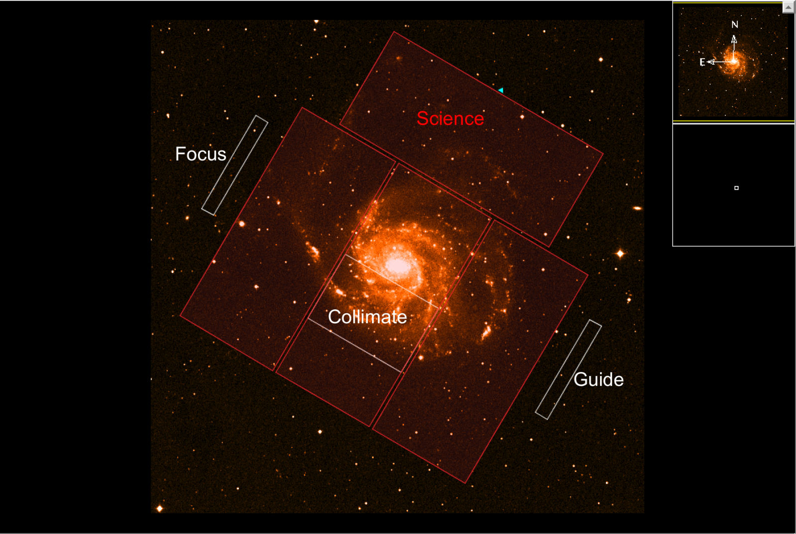
LBC: LBC Red and Blue has 4 options in the Field of View Sections. The Science field for LBC Red or Blue at the base position will put a red or blue overlay, respectively, of the science chips on the image. An additional white outline of the Science array will outline at offset position when the offset is highlighted in the Offset Iterator. The Collimate field will paint a white box outlining the collimation field located inside chip2 of the science array. The Focus and Guide fields will paint the 256 pixel x 2048 pixel technical chips on either side of the science array (the focus next to chip 3 of the science array, and the guide next to chip 1 of the science array).
 |
 |
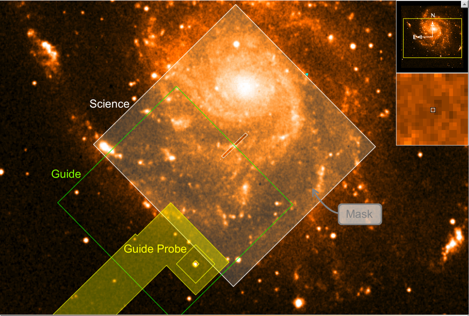
MODS: MODS1 and MODS2 overlays are identical. MODS has 3 overlays: Science, Mask, and Guide. Guide draws the guider patrol field (outlined in green), if a guide star has been selected will draw the guide probe footprint itself (yellow). The guide probe overlay will show the area the guide probe will vignette. The Science field is outlined in white. An additional white outline of the Science field will outline at offset position when the offset is highlighted in the Offset Iterator. If a mask is in the focal plane, the Mask Field of View will have a white shading with slits cut out for the mask. The mask will only shade in the original base position and not offset positions.
 |
 |
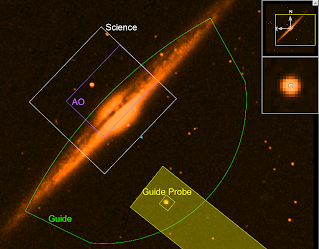
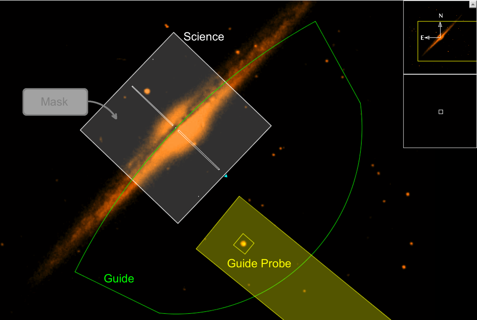
LUCI: LUCI1 and LUCI2 overlays are identical. LUCI has 4 overlays: Science, Mask, Guide, and AO. Guide draws the guider patrol field (outlined in green), if a guide star has been selected will draw the guide probe itself (yellow). The guide probe overlay will show the area the guide probe could vignette. The Science field is outlined in white. An additional white outline of the Science field will outline at offset position when the offset is highlighted in the Offset Iterator. If a mask is in the focal plane, the Mask Field of View will have a white shading with slits cut out for the mask. The mask will only shade in the original base position and not offset positions. The AO patrol field is outlined in purple.
 |
 |

