Filters
Page last updated: April 2026
There are two filter wheels in each LBC. Each wheel has 5 positions, and since 1 must remain free, at most 8 filters can be available in each LBC at any one time. The filter wheels and the cryostat are all mounted on the derotator, which tracks the sidereal rotation of the sky during an exposure. In LBCB there are a total of 7 filters and a pinhole mask that are all installed, and in LBCR there are a total of 10 filters available, of which 8 are installed at any given time. Currently the TiO_784 and CN_817 filters are installed in LBC Red only by request. It is important that the partner coordinators and observers communicate the need for these filters to LBTO staff well in advance of the run, to allow scheduling of a filter swap. Please contact the sciops group in advance if you have an interest in manufacturing and/or installing a custom filter.
*Broadband interference filters in collimated beam.
**Narrowband interference filters, shown in the LBC’s converging beam.
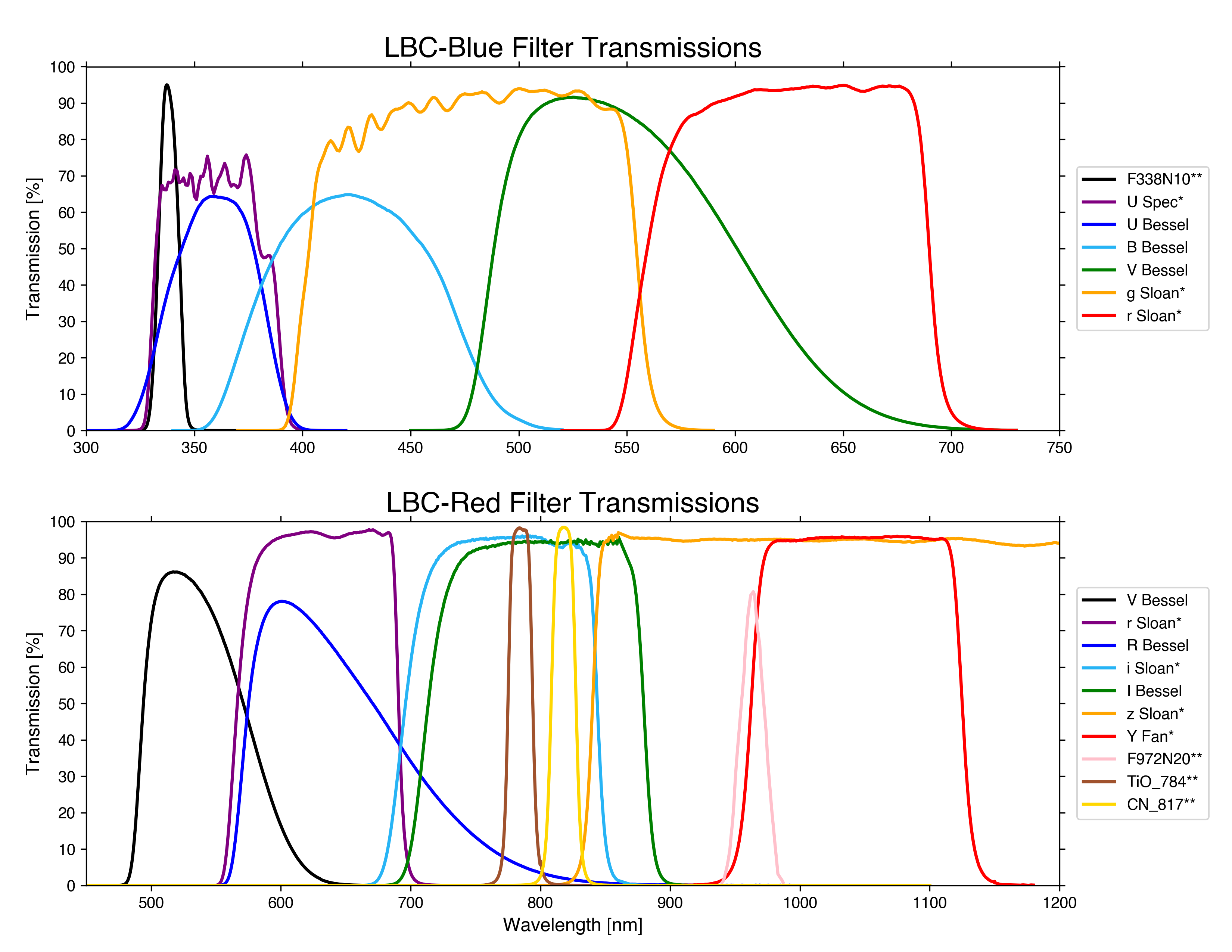
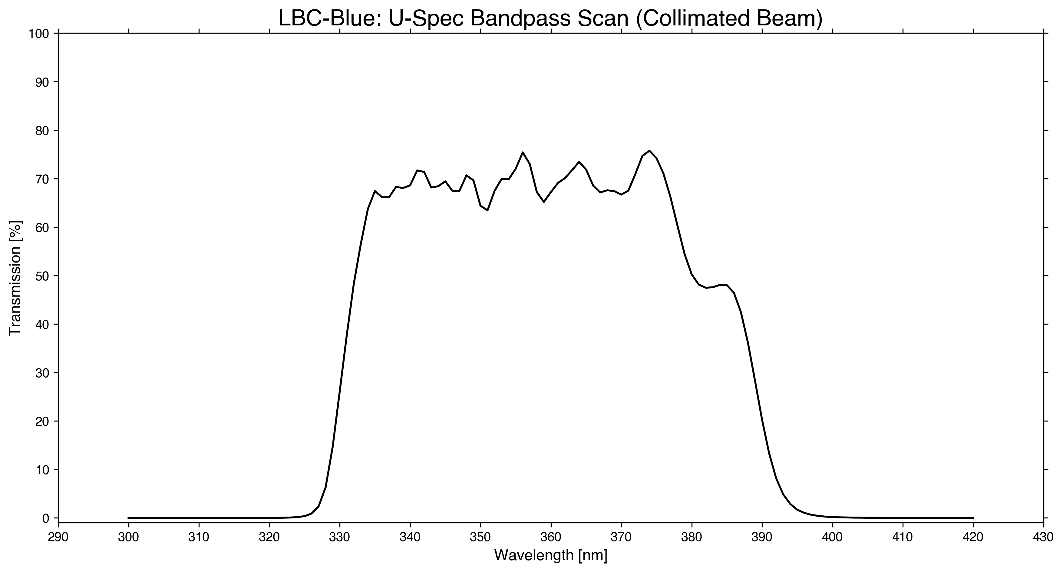
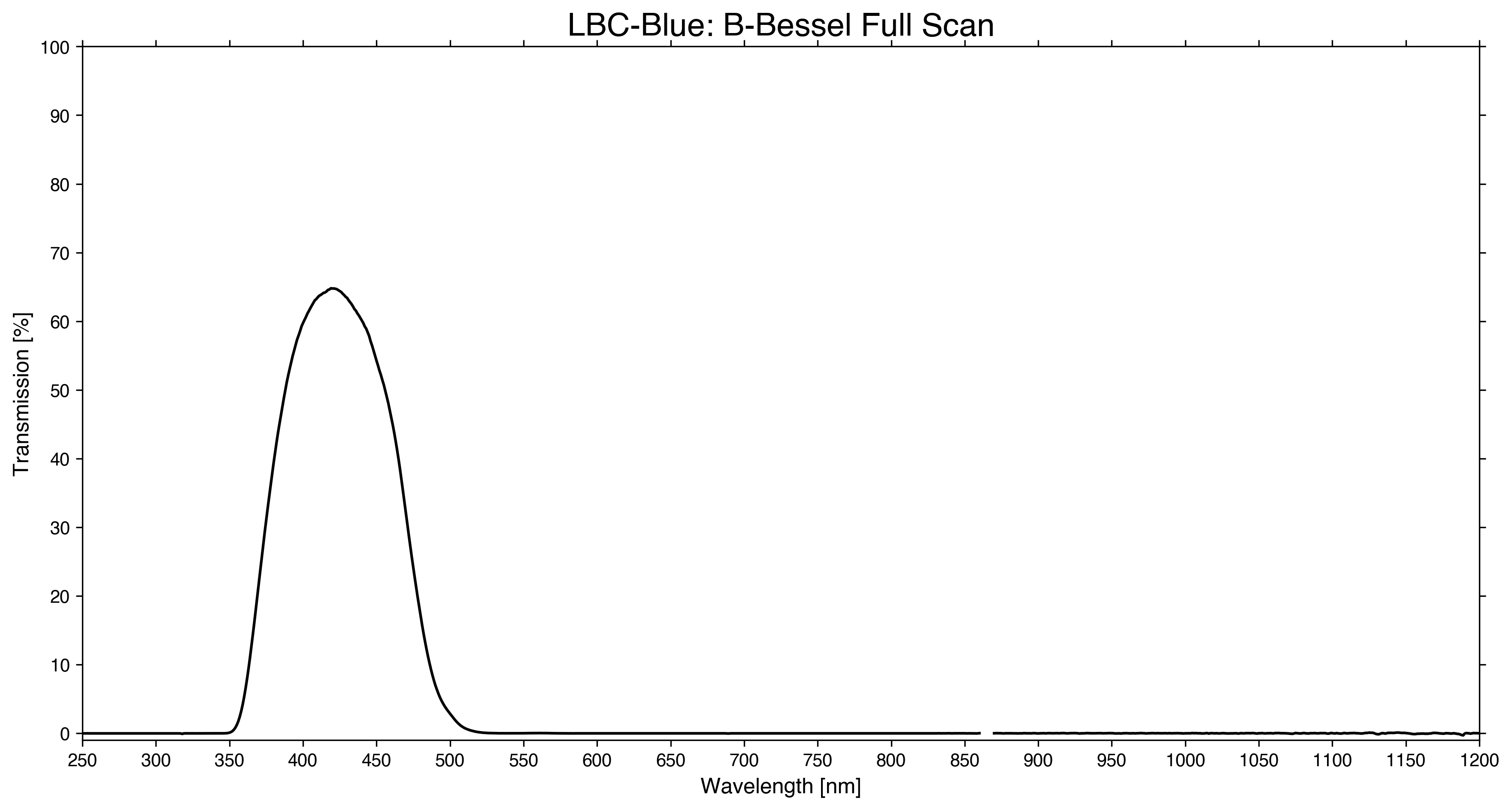
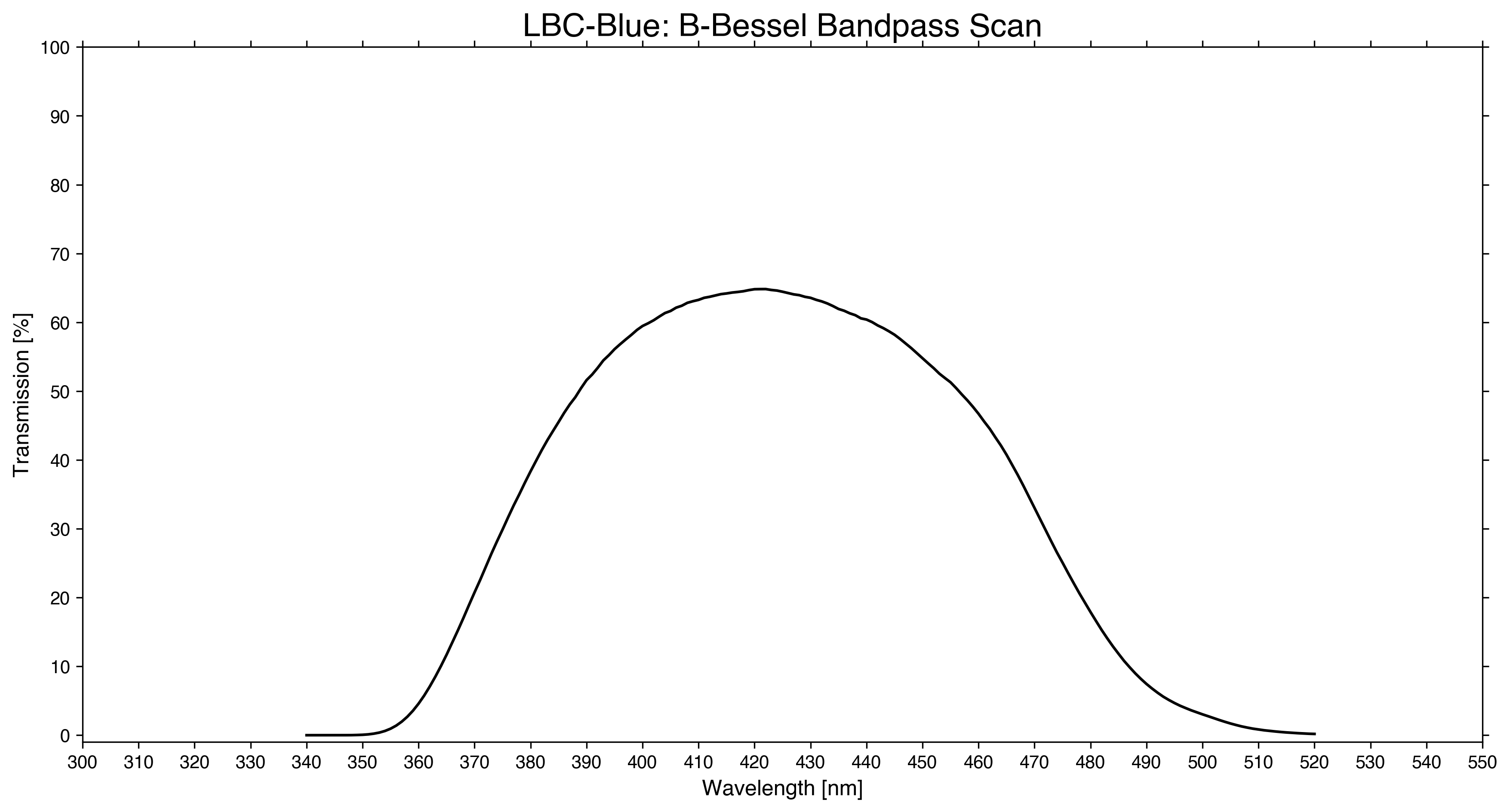
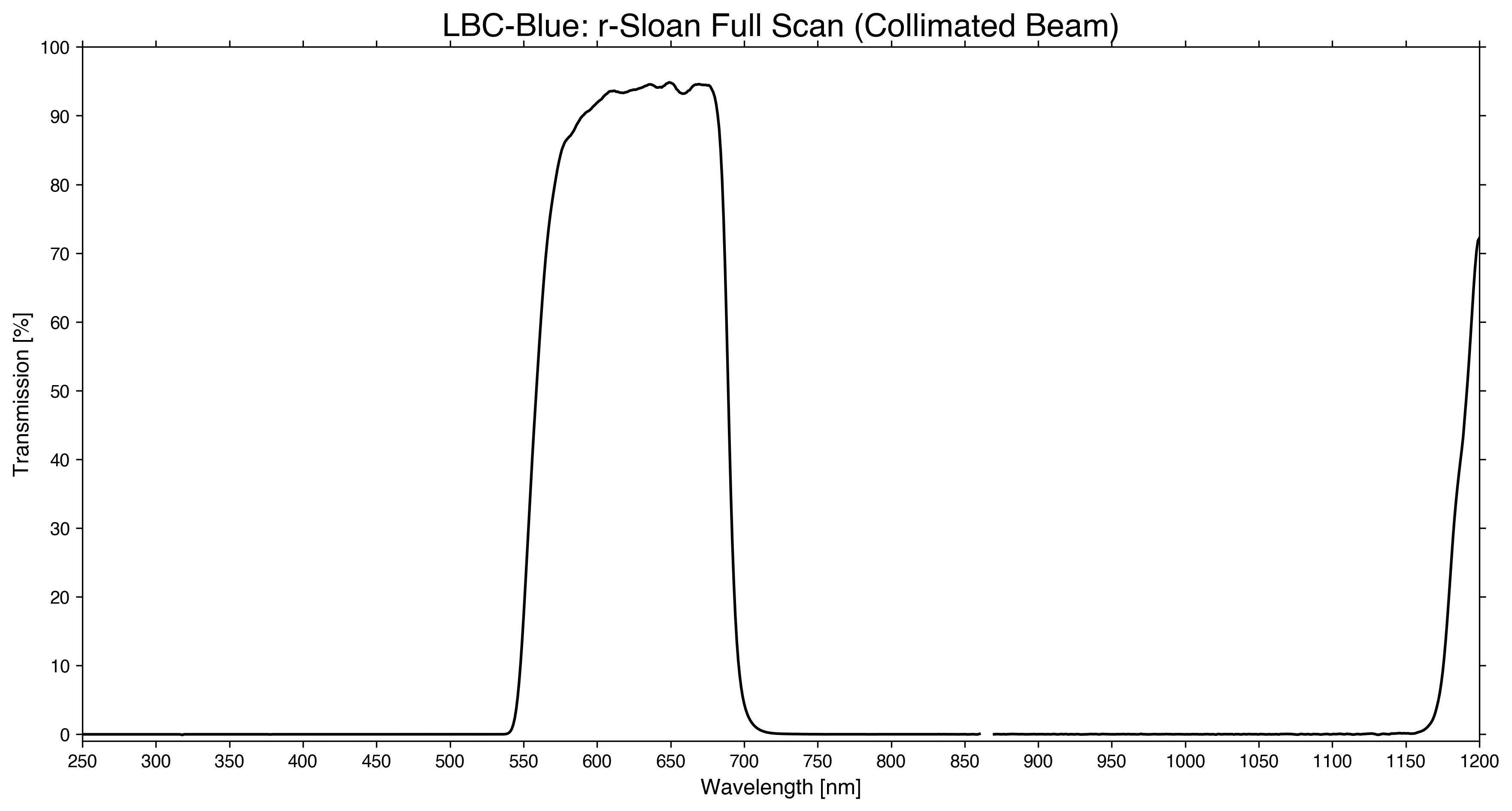
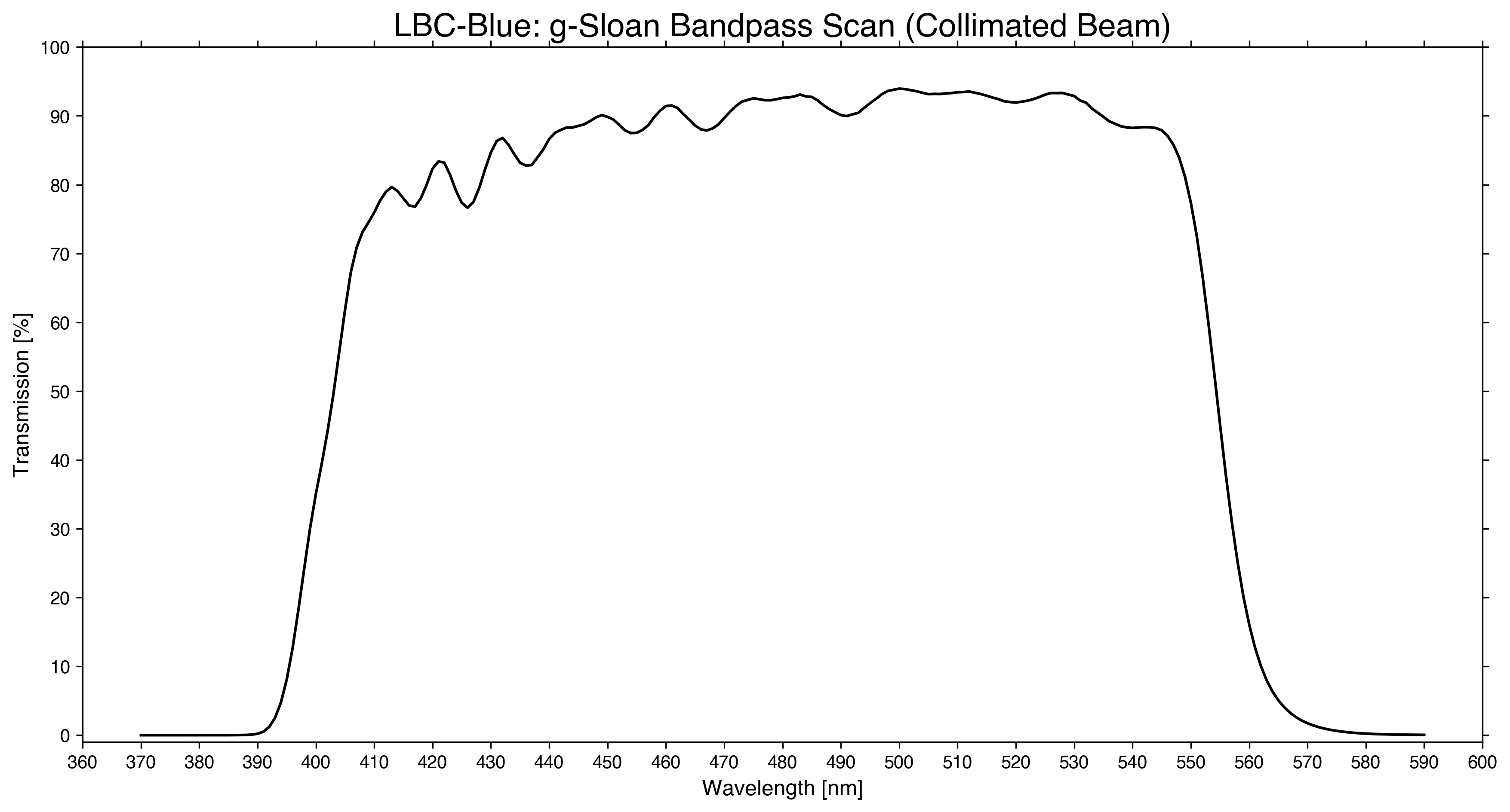
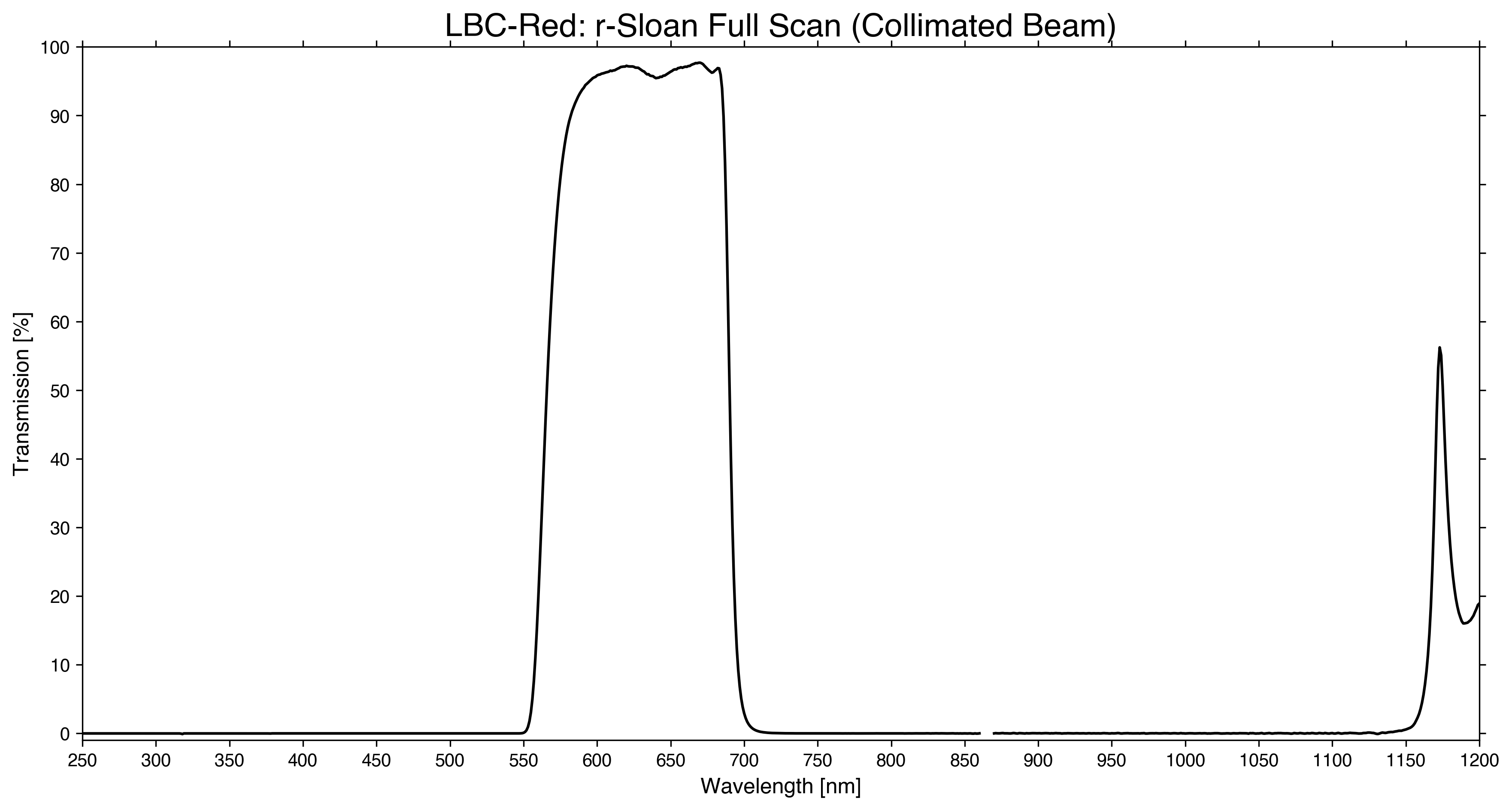
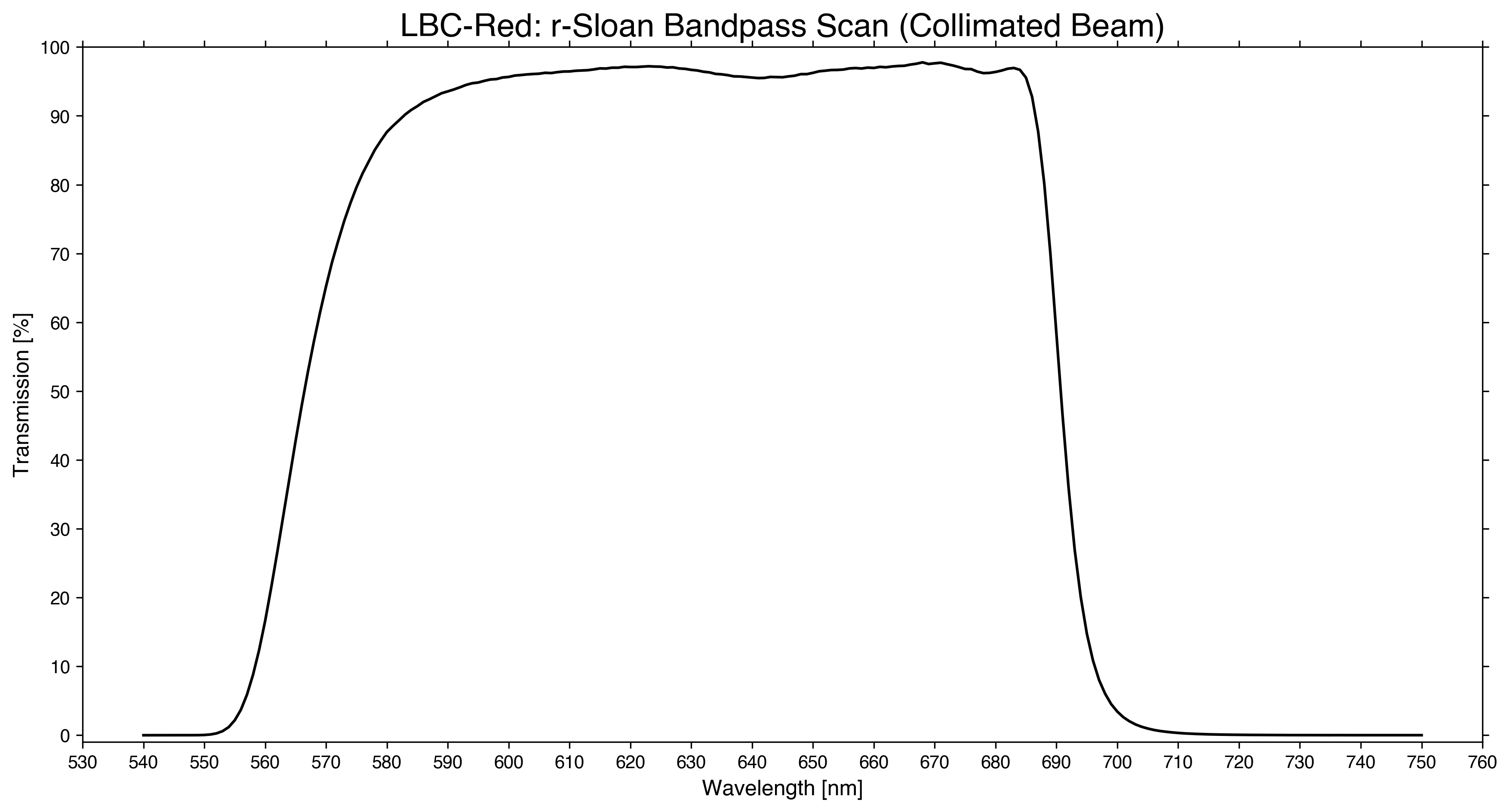
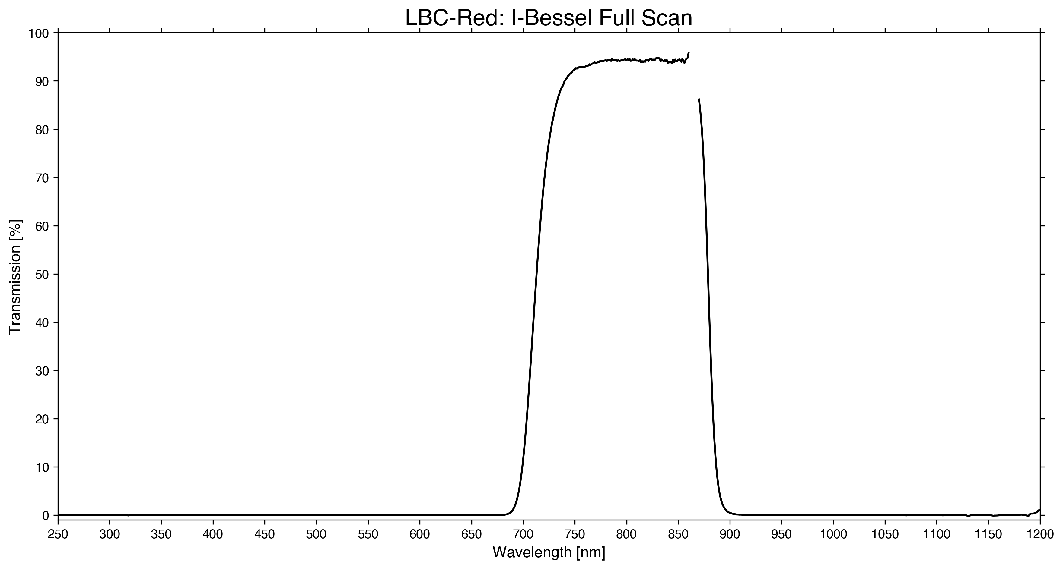
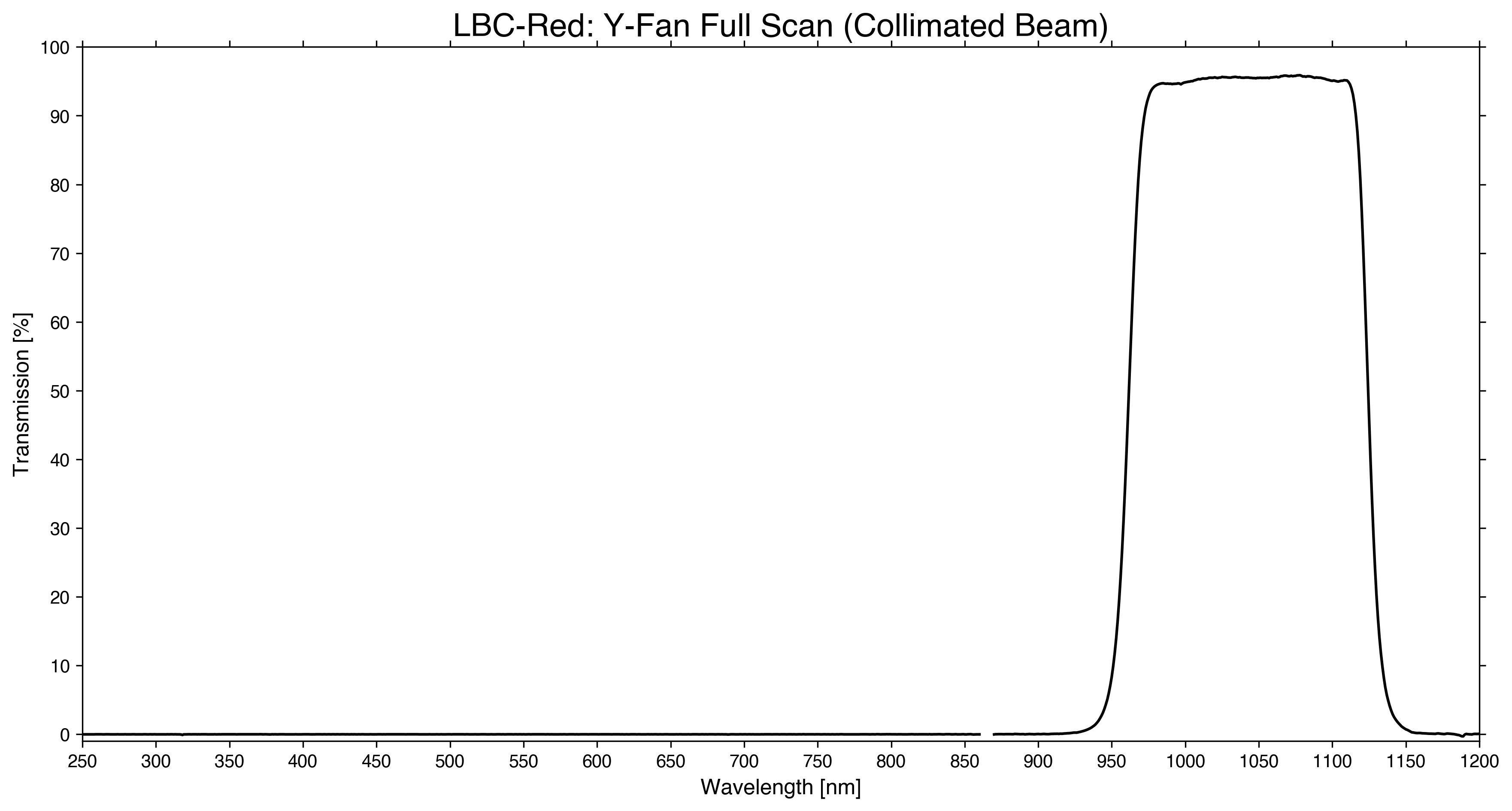
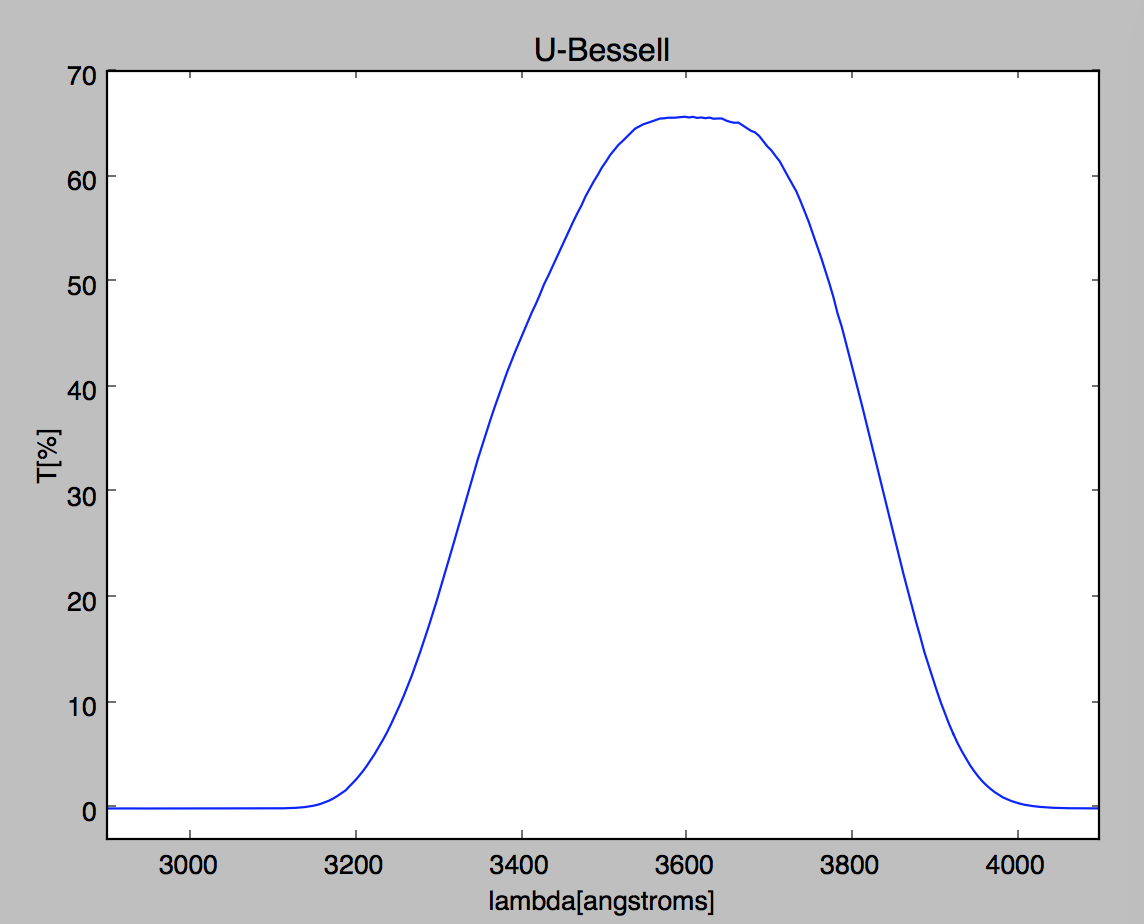
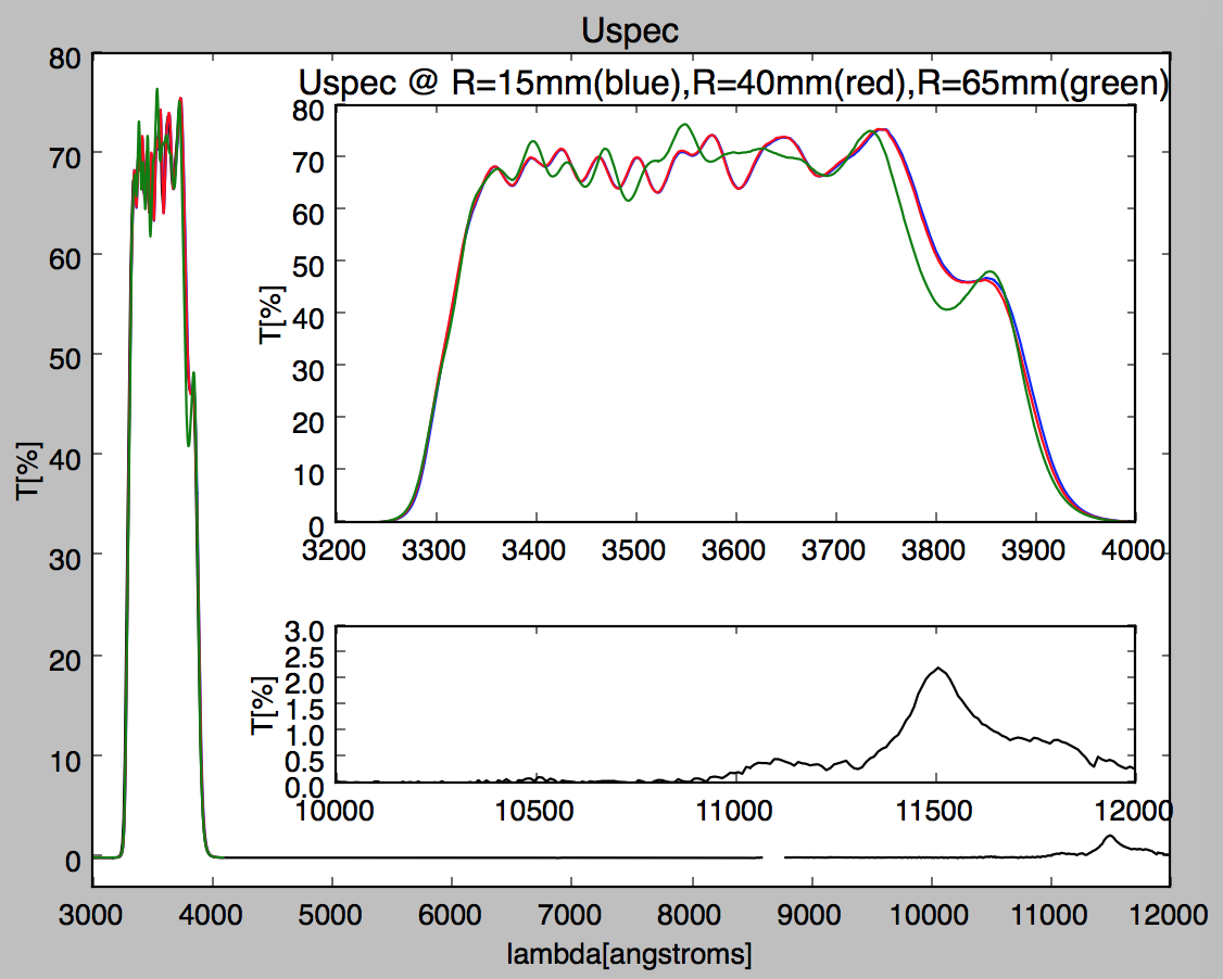
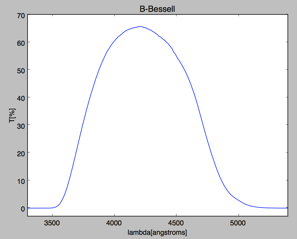
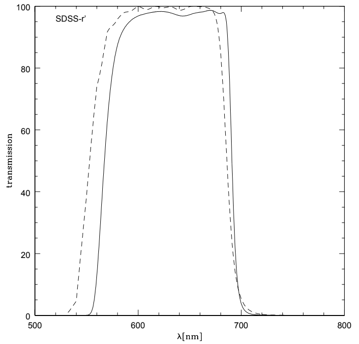
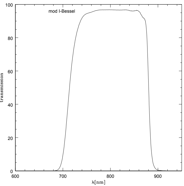
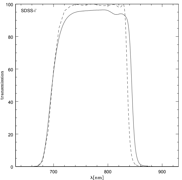
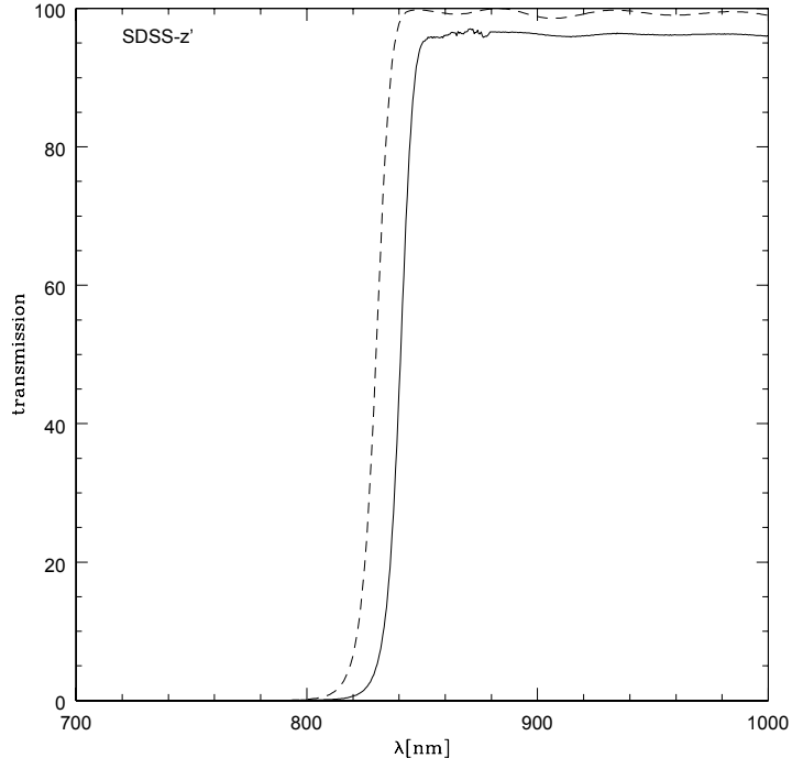
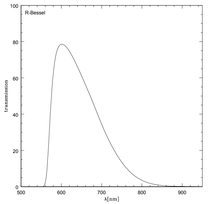
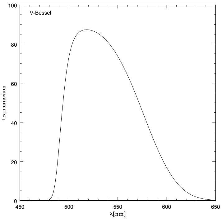
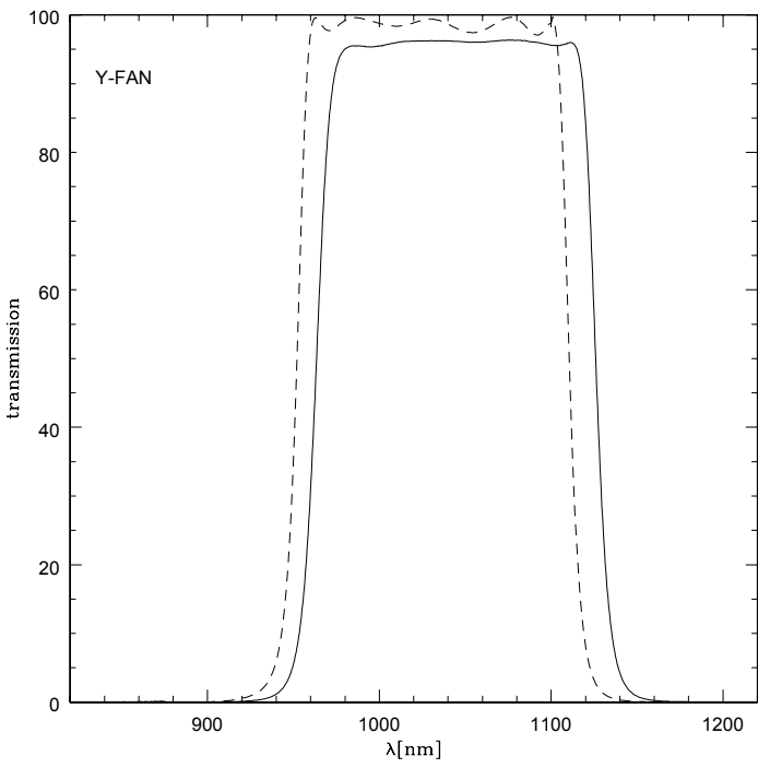
In the plot above we show the transmission curves for all filters available in each instrument. These were all measured during the summer shutdown of 2025 using a Perkin-Elmer Lambda 9 spectrometer at NOIRLab. All broadband filters are shown in a collimated beam, while narrowband filters are corrected for a converging beam (see below). Note that there is no data from 860-870nm because of a broken motor in the spectrometer that switches between the visible light and infrared source (it was manually moved between scans).
| Filters in LBC Blue | |||||||||
|---|---|---|---|---|---|---|---|---|---|
| Position | Filter Name | Plot | Data | Interference? | CWL [A] | FWHM [A] | 50% cut-on [A] | 50% cut-off [A] | Peak Trans. [%] |
| 11 | Empty | N/A | N/A | N/A | N/A | N/A | N/A | N/A | N/A |
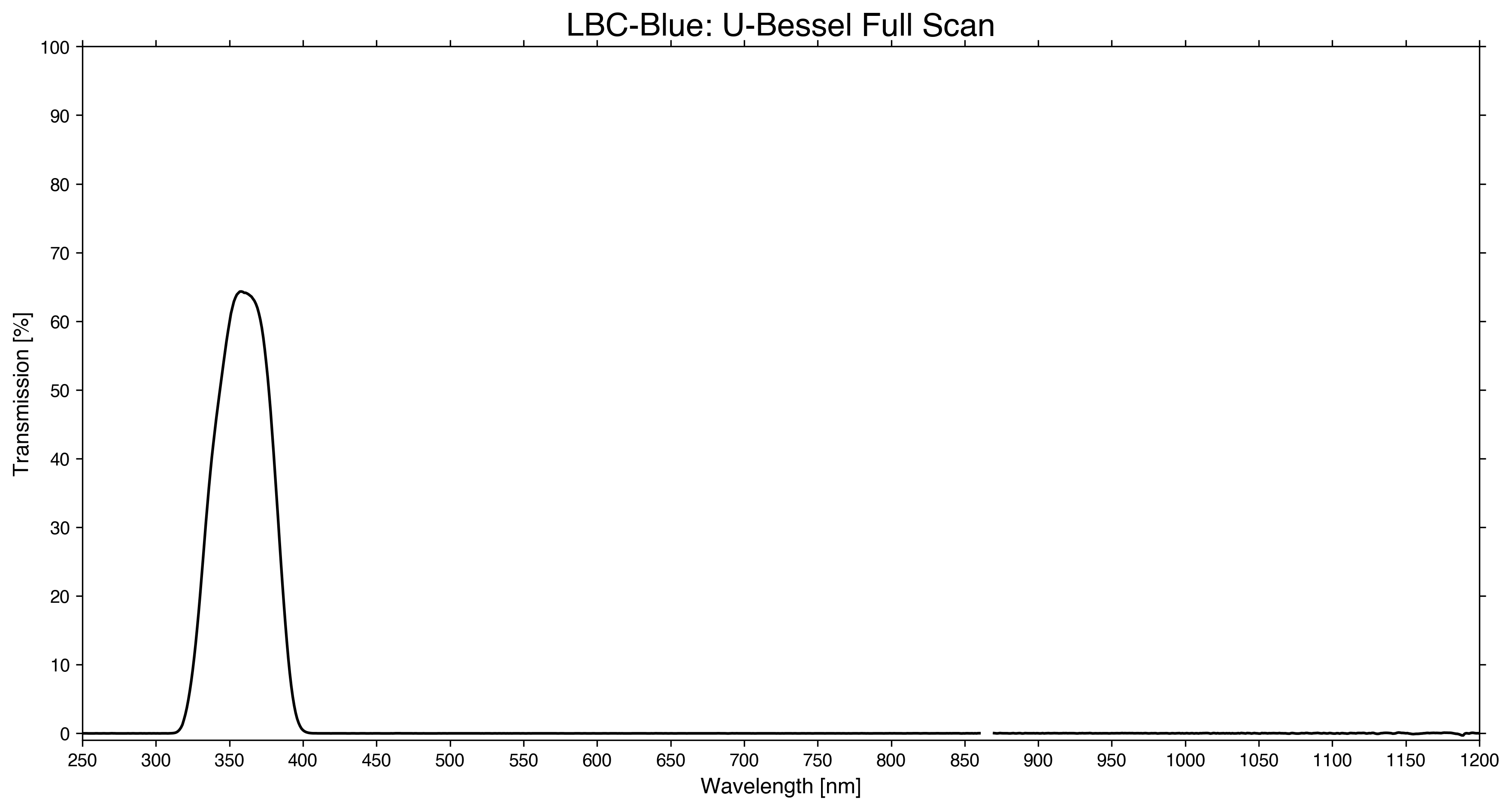
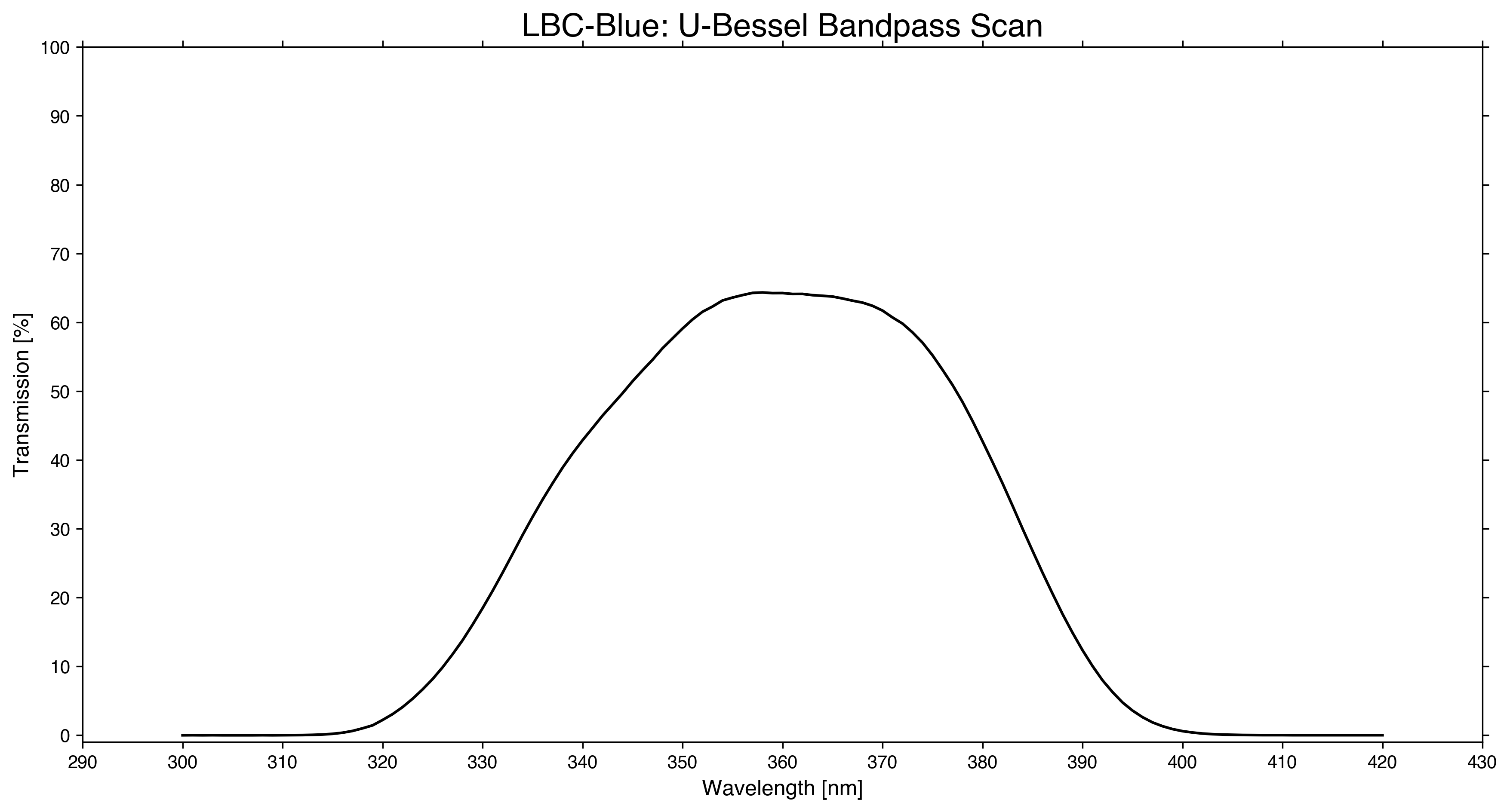
| 12 | U-Bessel | full/bandpass | full/bandpass | No | 3592.7 | 481.7 | 3351.8 | 3833.5 | 64.3% |
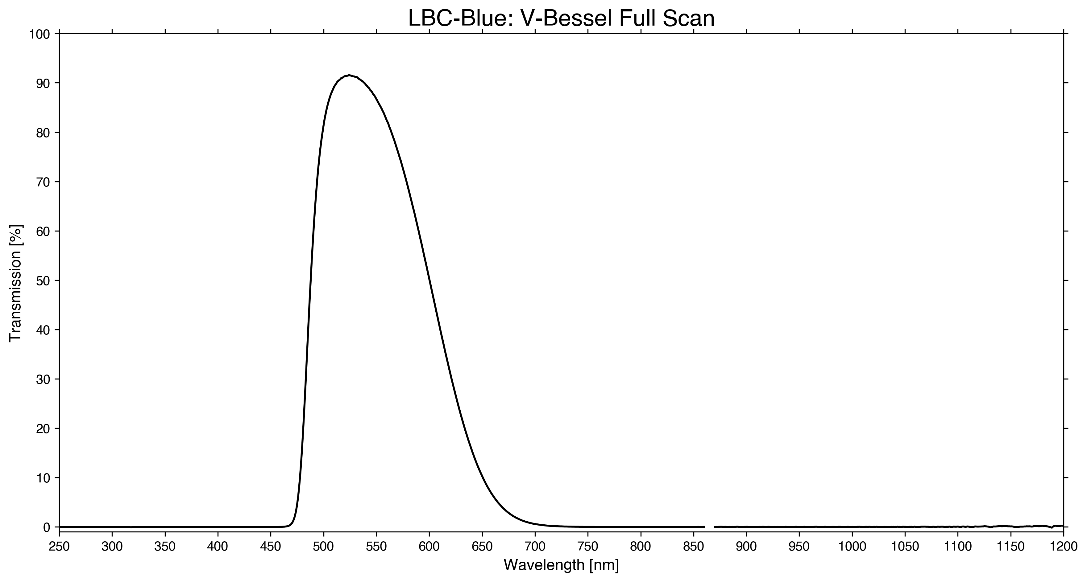
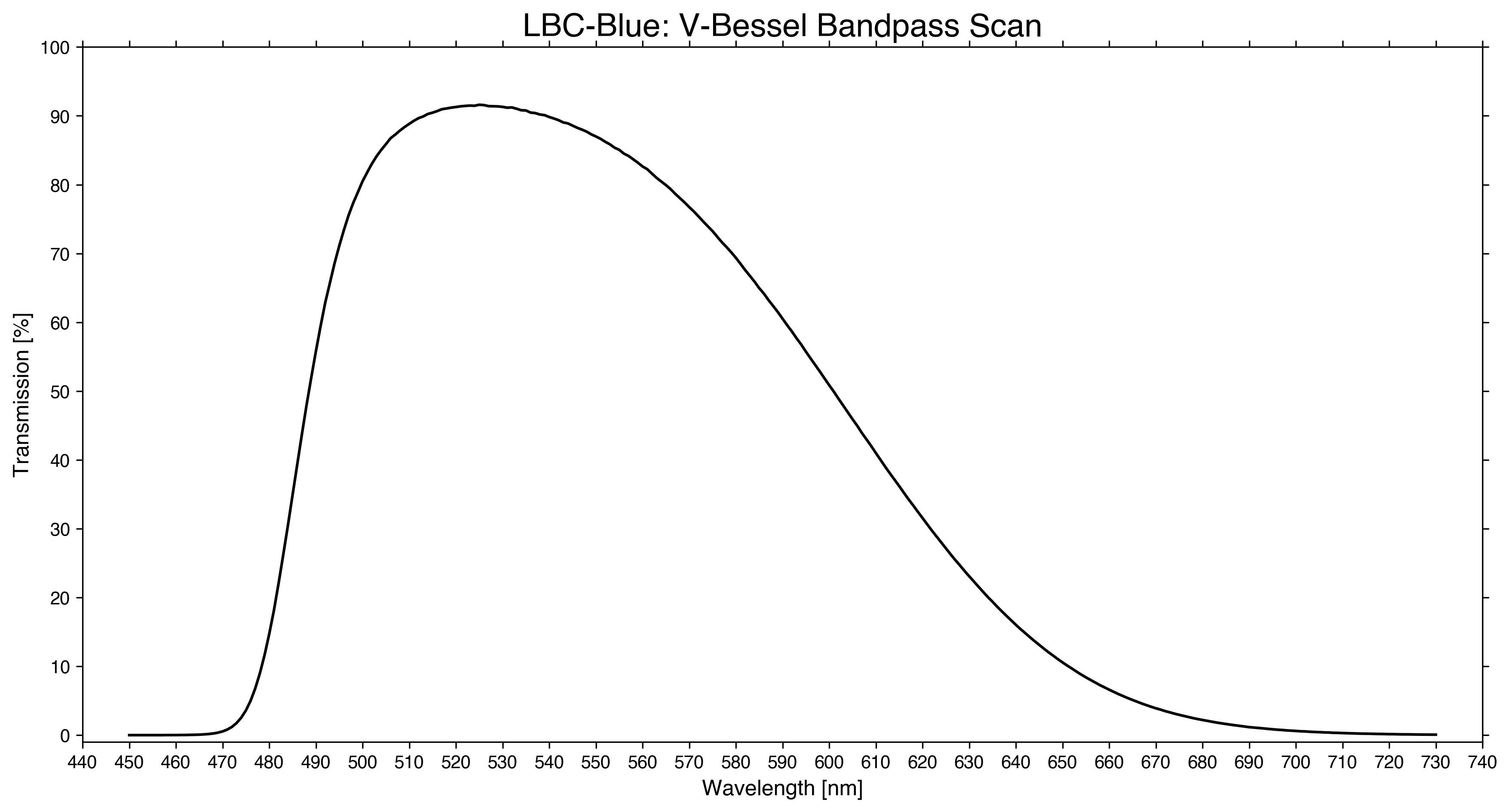
| 13 | V-Bessel | full/bandpass | full/bandpass | No | 5463.1 | 1176.4 | 4874.9 | 6051.3 | 91.6% |
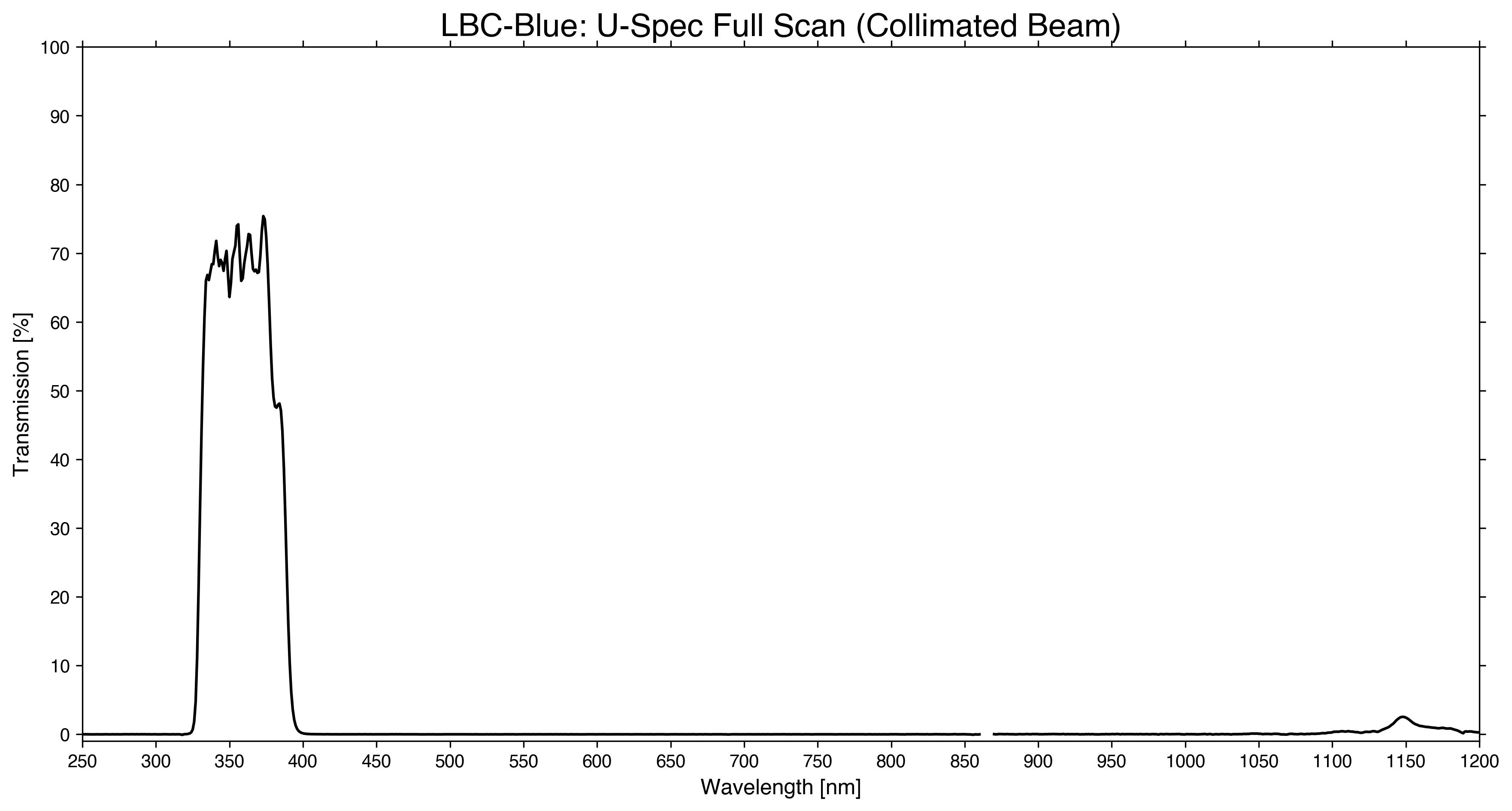
| 14 | SDT_Uspec | full/bandpass | full/bandpass | Yes | 3593.7 | 567.0 | 3310.2 | 3877.2 | 75.7% |
| 15 | B-Bessel | full/bandpass | full/bandpass | No | 4234.0 | 939.5 | 3764.3 | 4703.7 | 64.8% |
| 21 | Empty | N/A | N/A | N/A | N/A | N/A | N/A | N/A | N/A |
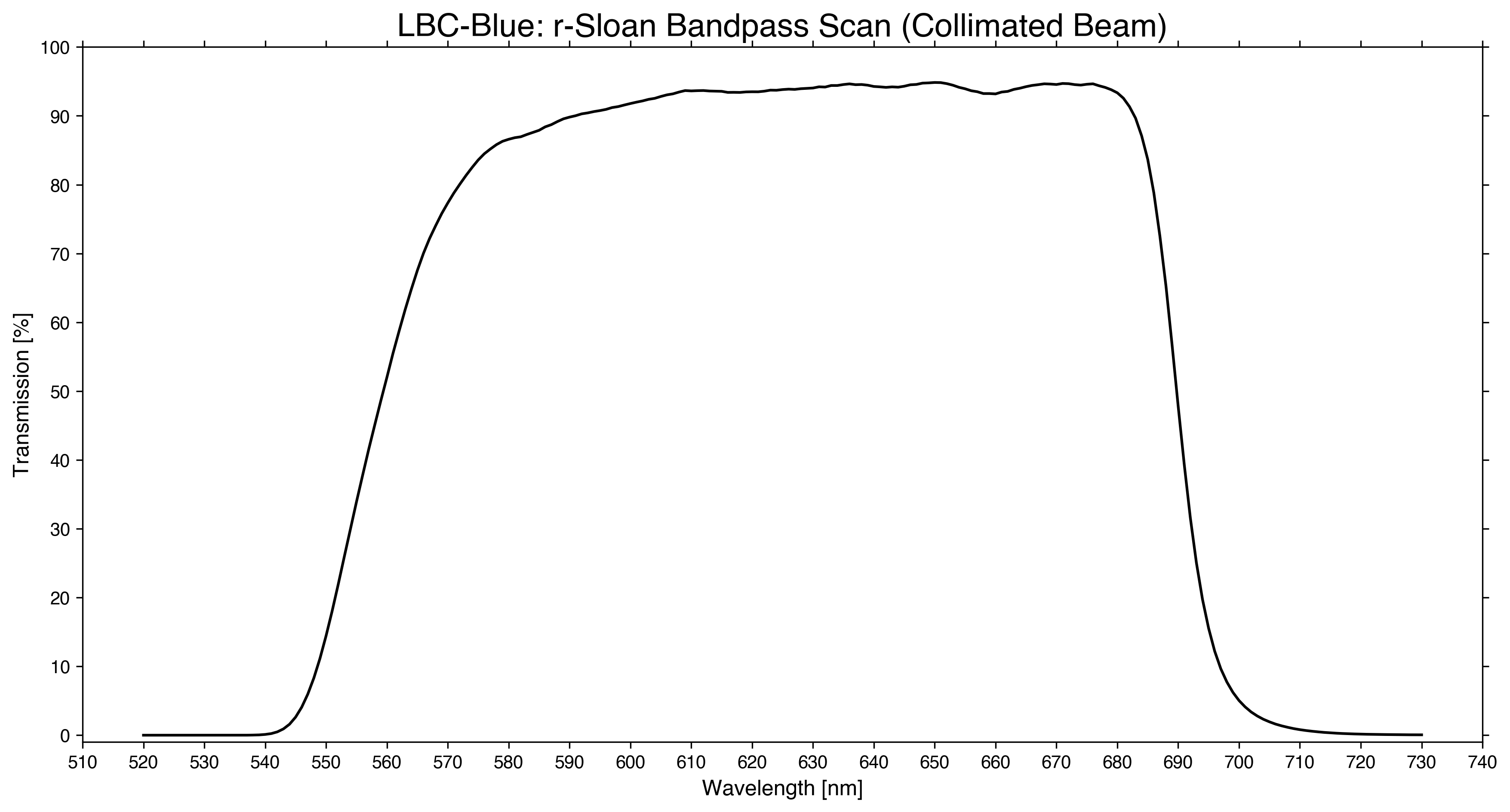
| 22 | r-Sloan1 | full/bandpass | full/bandpass | Yes | 6243.6 | 1313.8 | 5586.7 | 6900.5 | 94.8% |
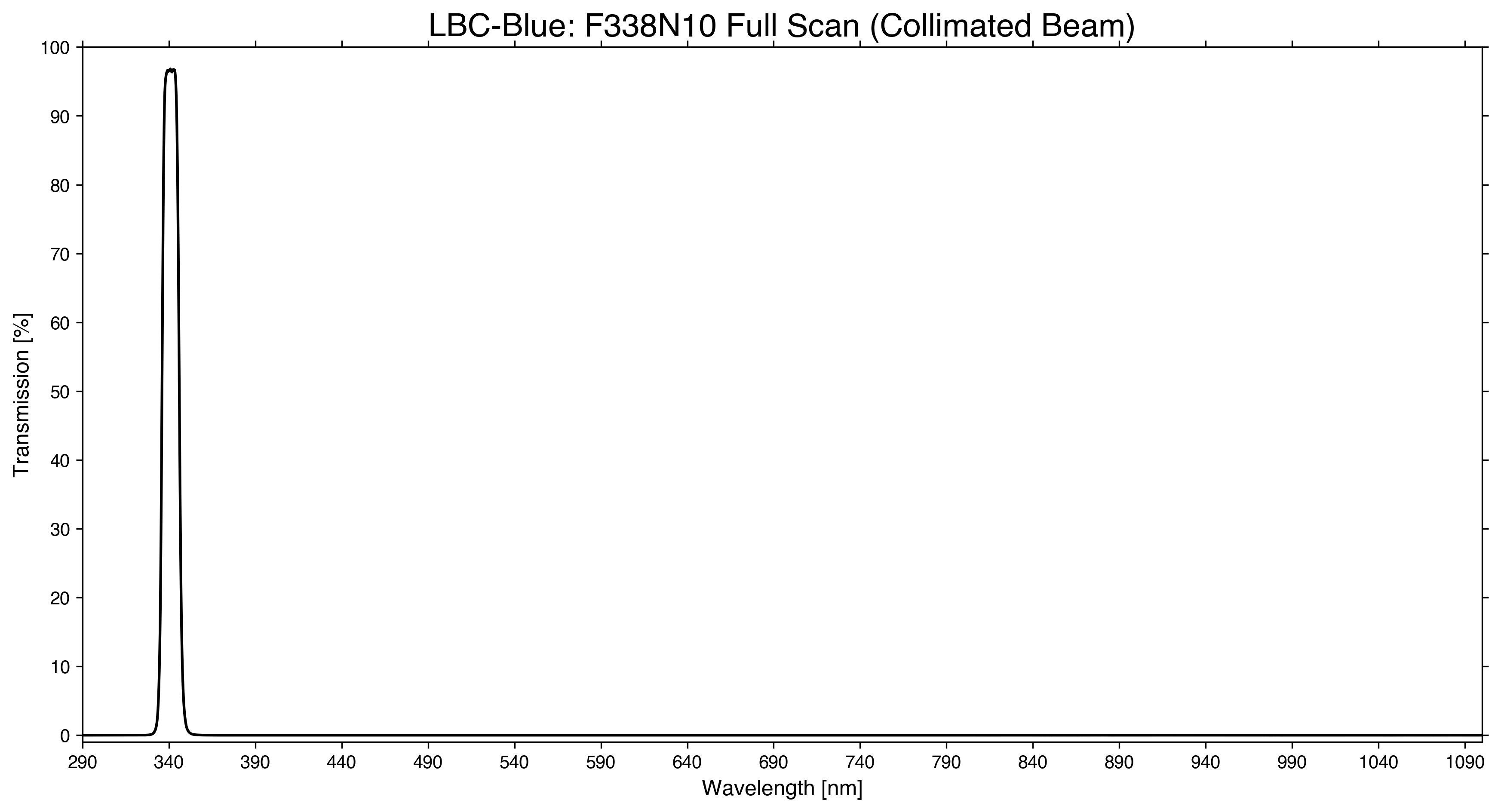
| 23 | F338N10 (coll) | full | full | Yes | 3409.8 | 101.2 | 3359.1 | 3460.4 | 96.8% |
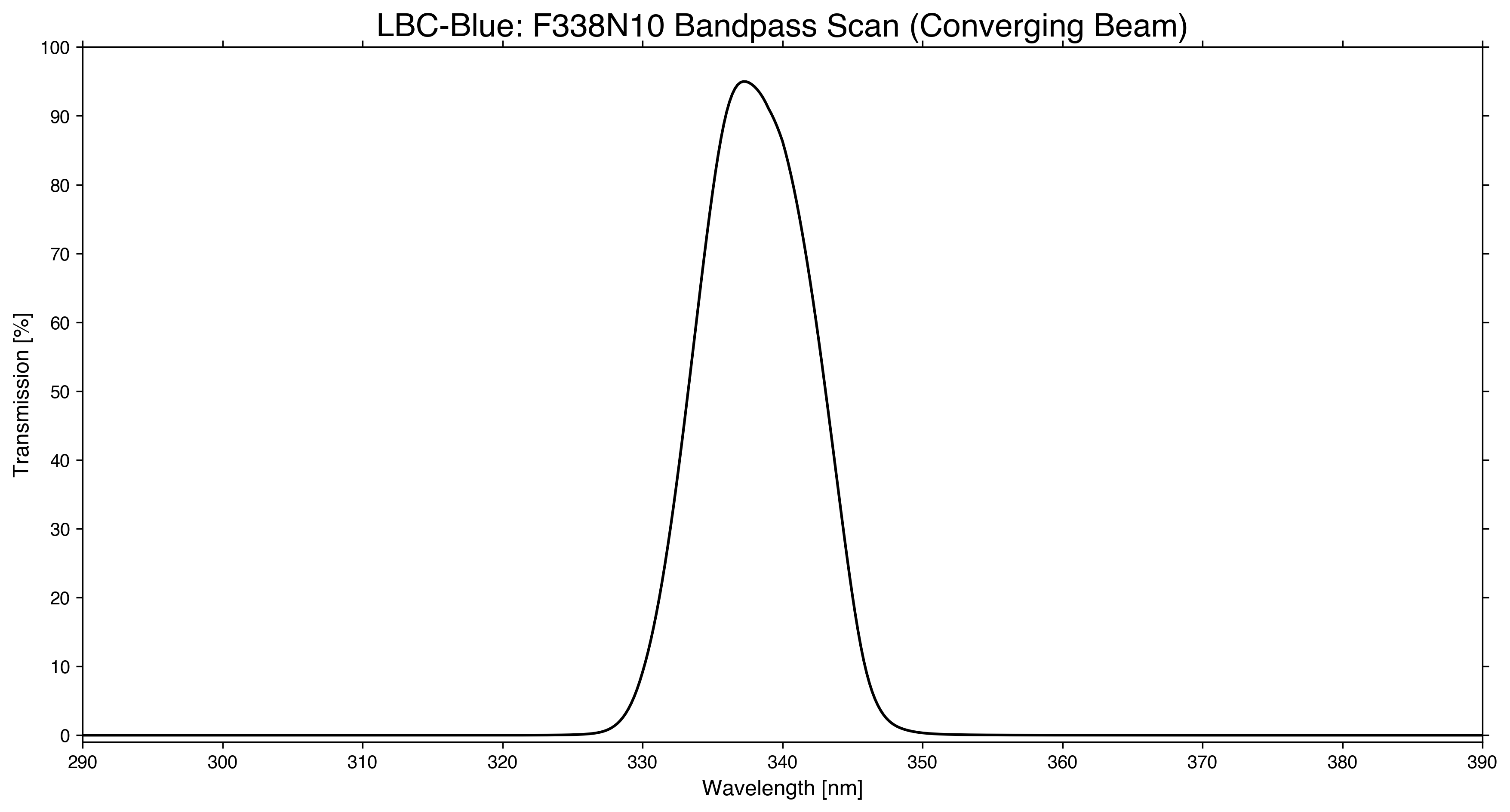
| F338N10 (conv) | bandpass | bandpass | 3381.7 | 101.2 | 3331.1 | 3432.3 | 95.0% | ||
| 24 | Pinhole | N/A | N/A | N/A | N/A | N/A | N/A | N/A | N/A |
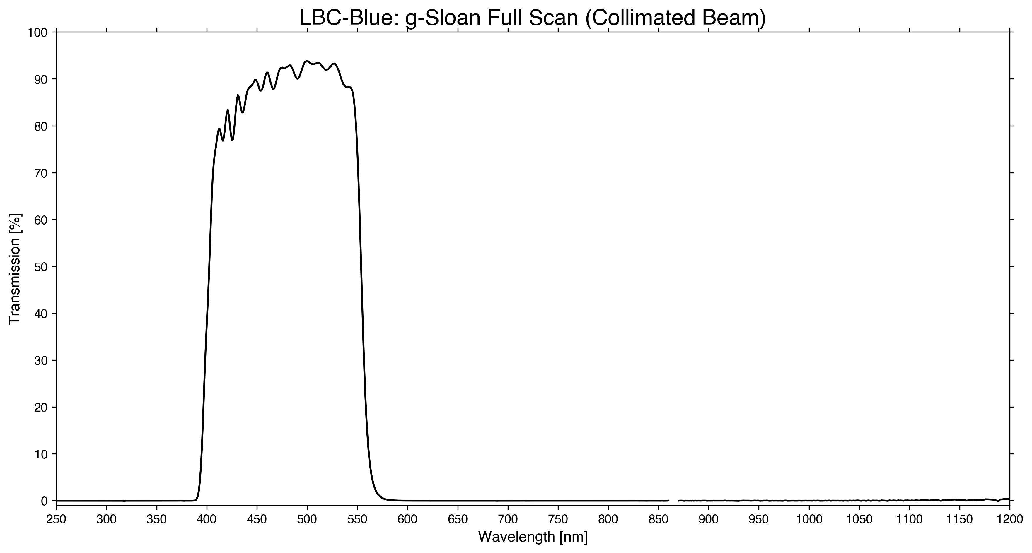
| 25 | g-Sloan1 | full/bandpass | full/bandpass | Yes | 4786.4 | 1522.4 | 4025.2 | 5547.6 | 94.0% |
| Filters in LBC Red | |||||||||
|---|---|---|---|---|---|---|---|---|---|
| Position | Filter Name | Plot | Data | Interference? | CWL [A] | FWHM [A] | 50% cut-on [A] | 50% cut-off [A] | Peak Trans. [%] |
| 11 | Empty | N/A | N/A | N/A | N/A | N/A | N/A | N/A | N/A |
| 12 | r-Sloan | full/bandpass | full/bandpass | Yes | 6285.1 | 1246.0 | 5662.1 | 6908.0 | 97.8% |
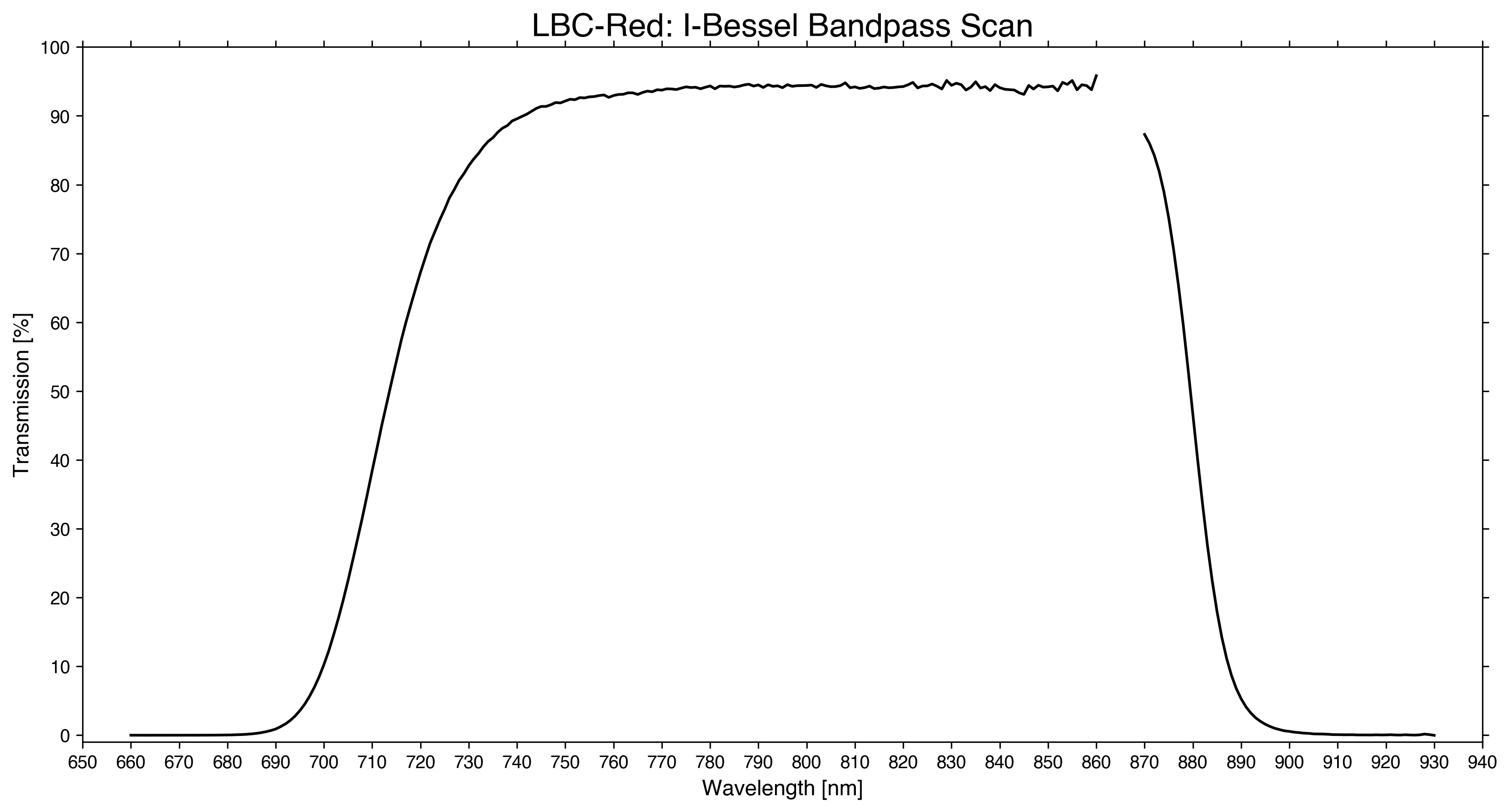
| 13 | I-Bessel | full/bandpass | full/bandpass | No | 7963.3 | 1670.6 | 7128.0 | 8798.5 | 95.1% |
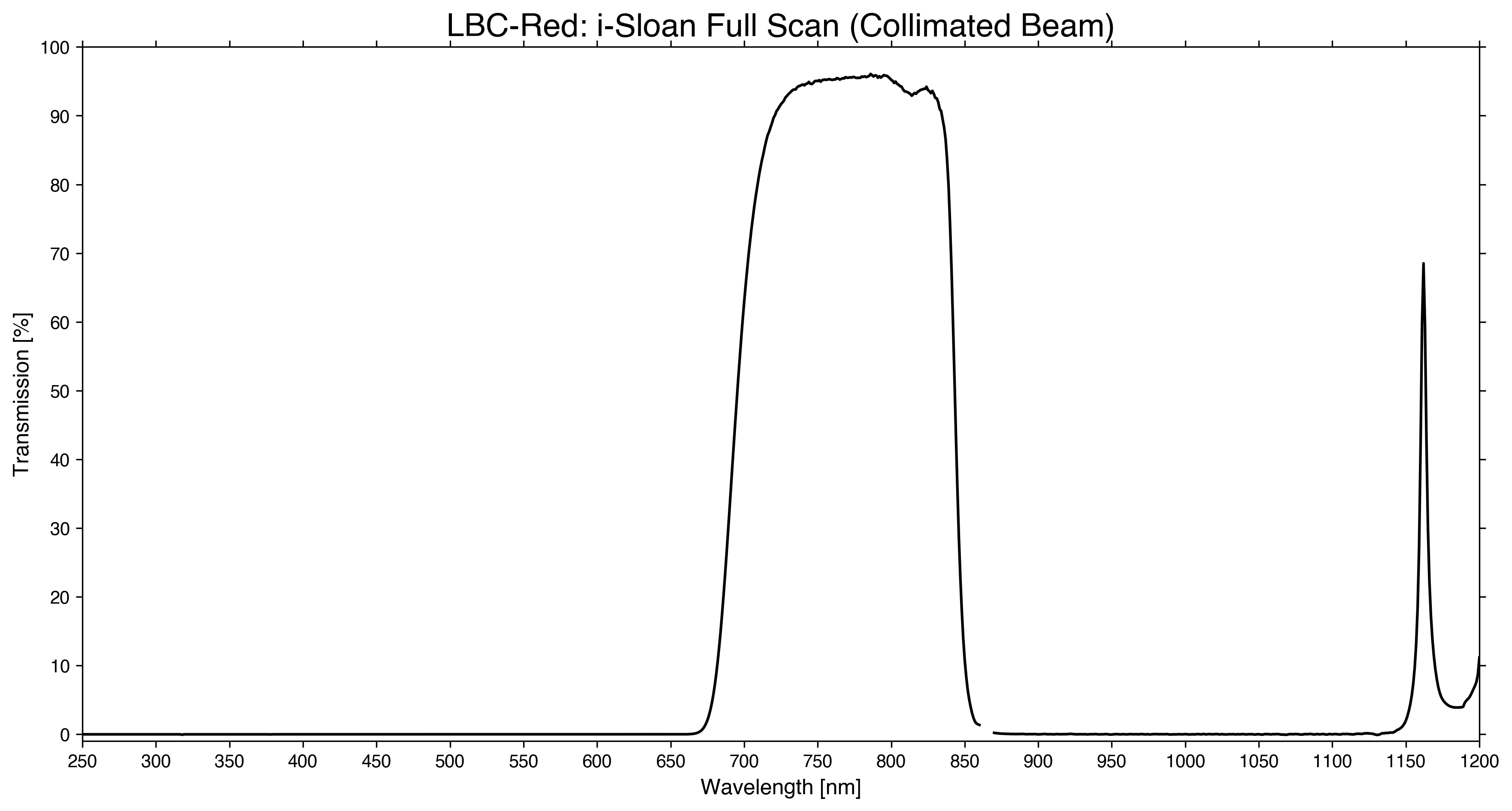
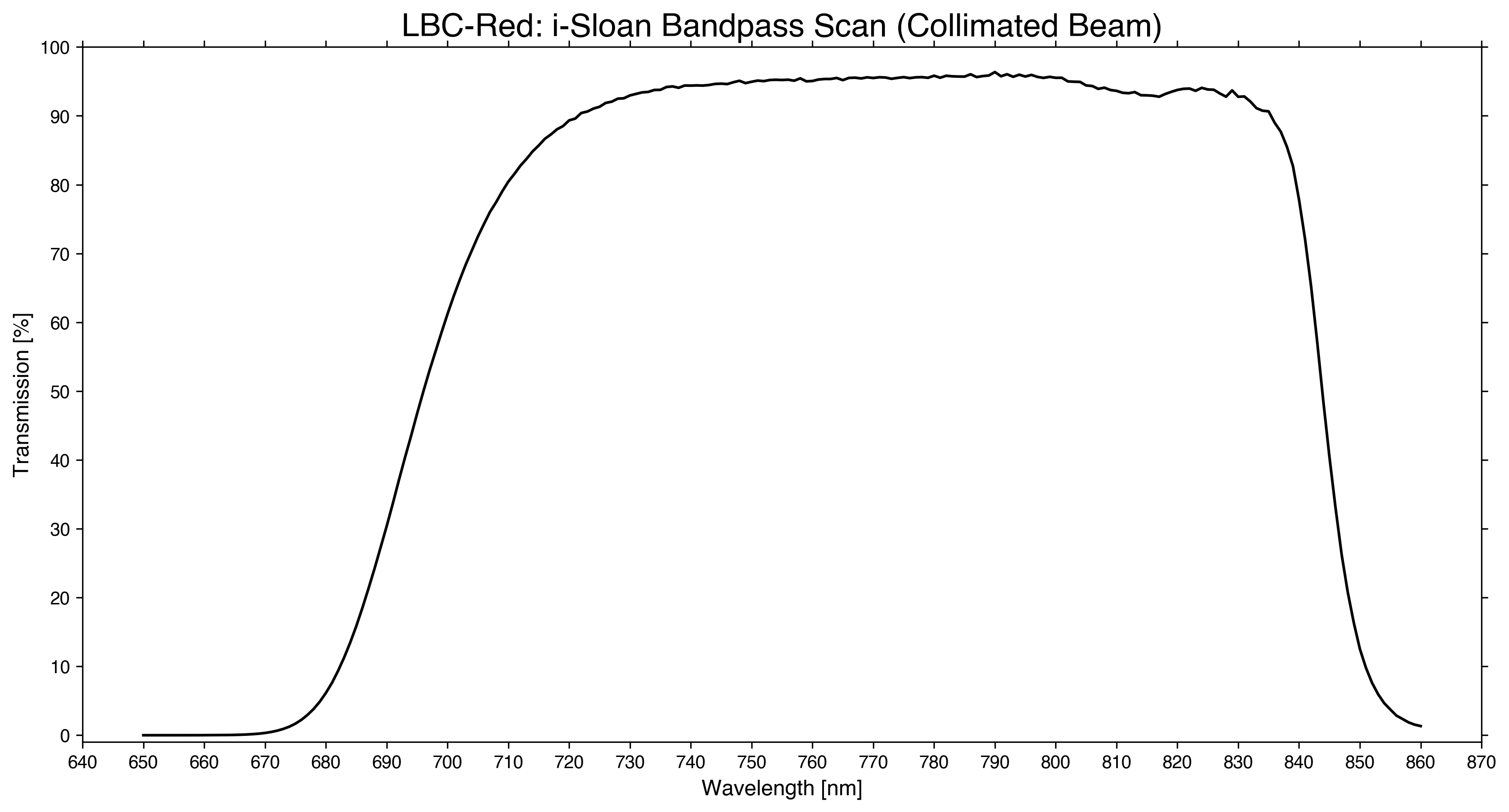
| 14 | i-Sloan | full/bandpass | full/bandpass | Yes | 7697.5 | 1485.7 | 6954.7 | 8440.4 | 96.4% |
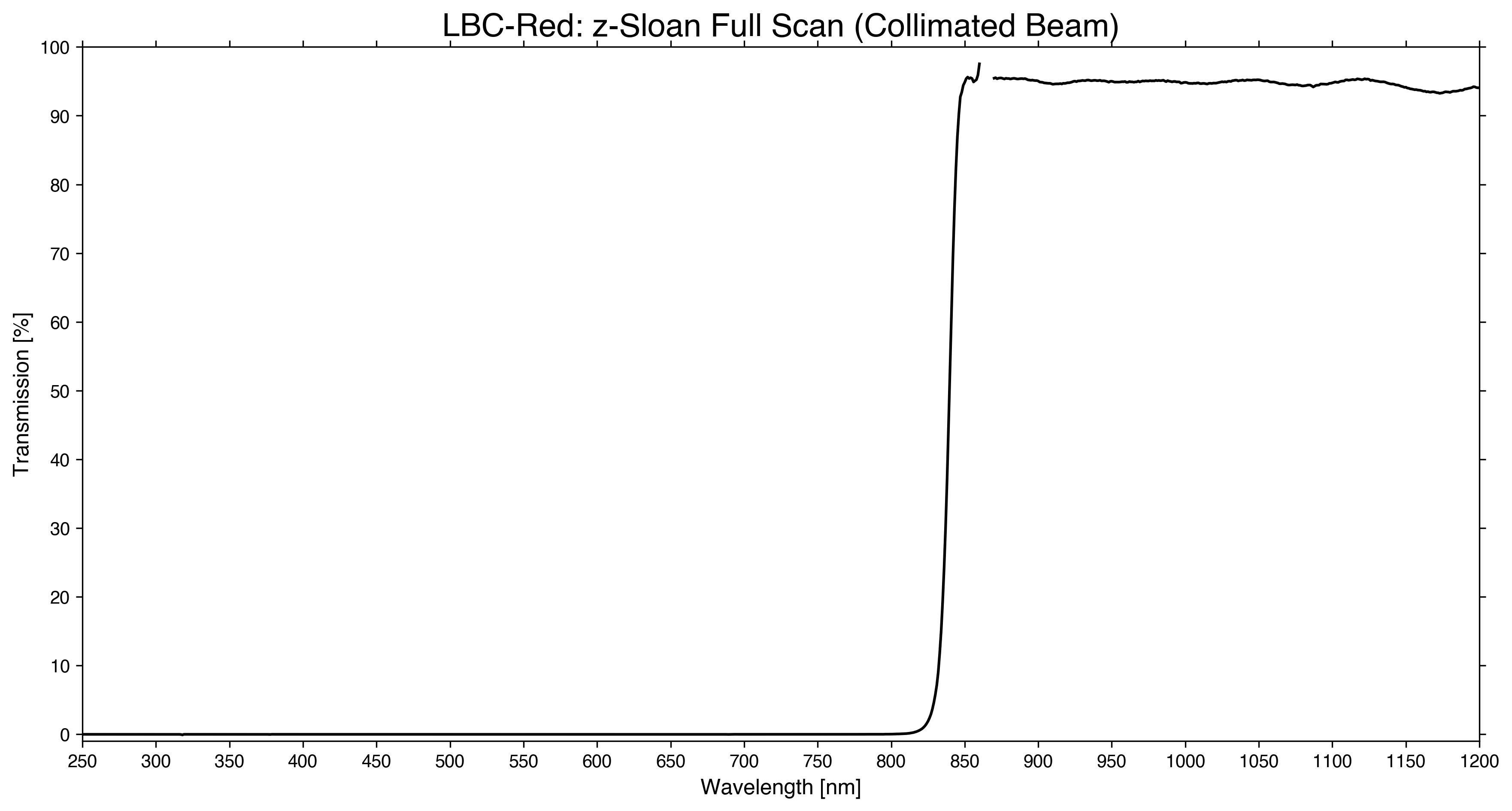
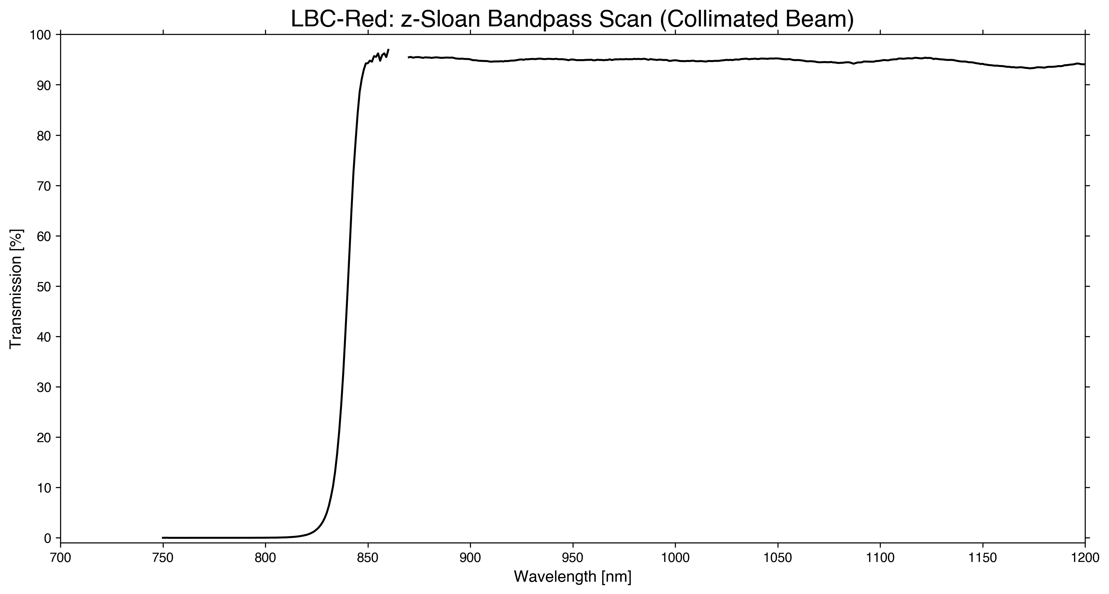
| 15 | z-Sloan | full/bandpass | full/bandpass | Yes | N/A | N/A | 8399.9 | N/A | 96.2% |
| 21 | Empty | N/A | N/A | N/A | N/A | N/A | N/A | N/A | N/A |
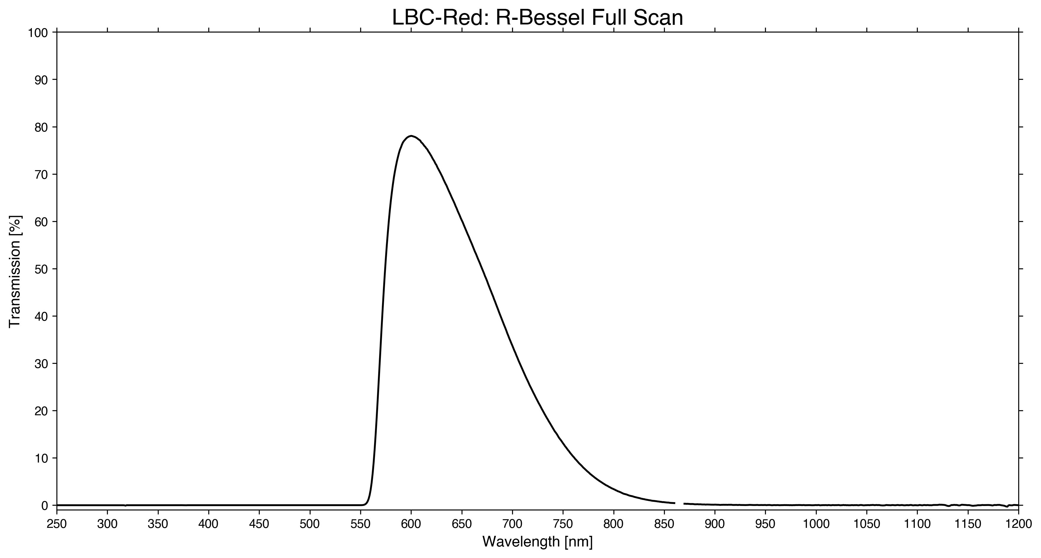
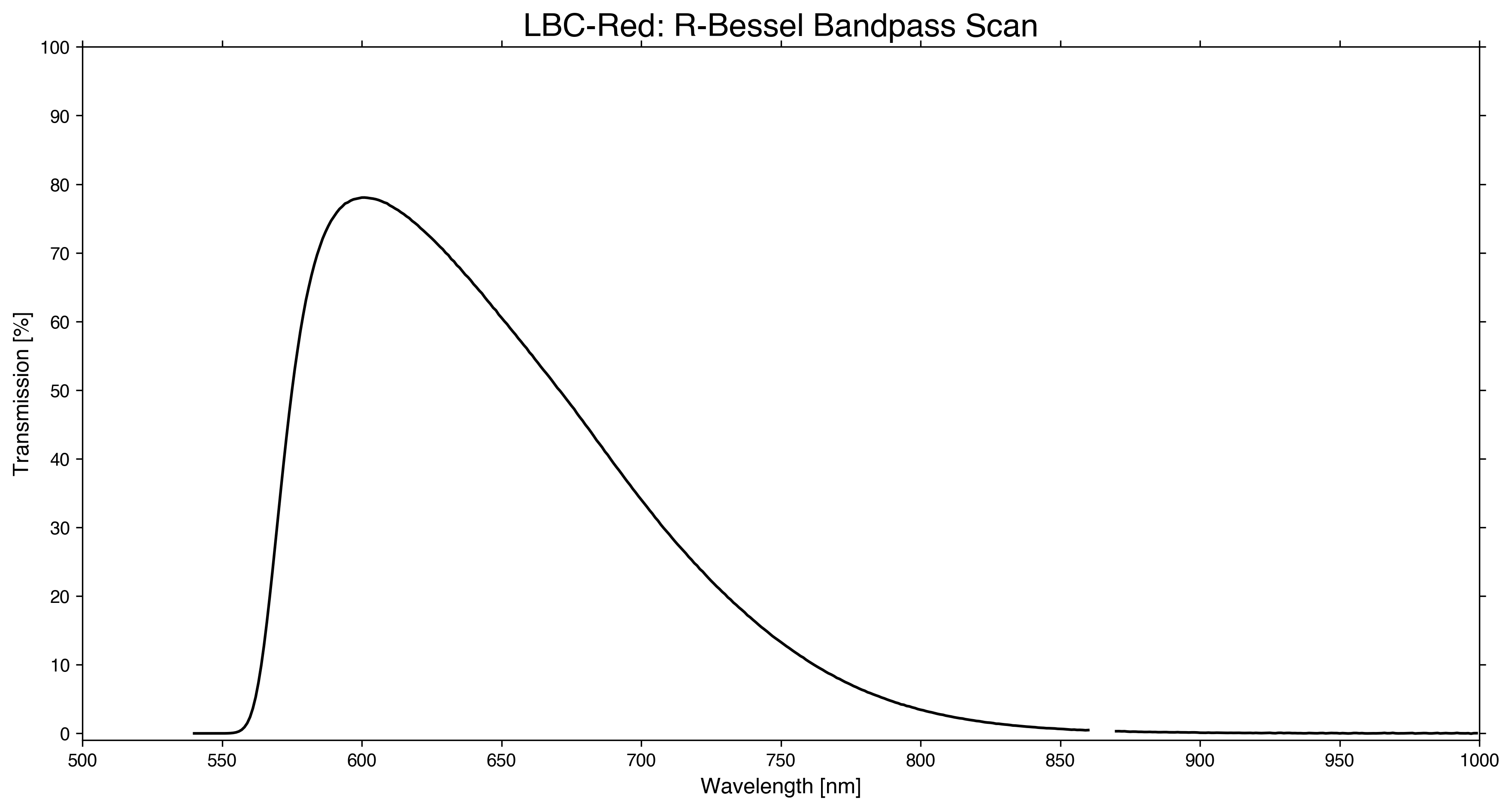
| 22 | R-Bessel | full/bandpass | full/bandpass | No | 6313.2 | 1187.2 | 5719.3 | 6907.1 | 78.1% |
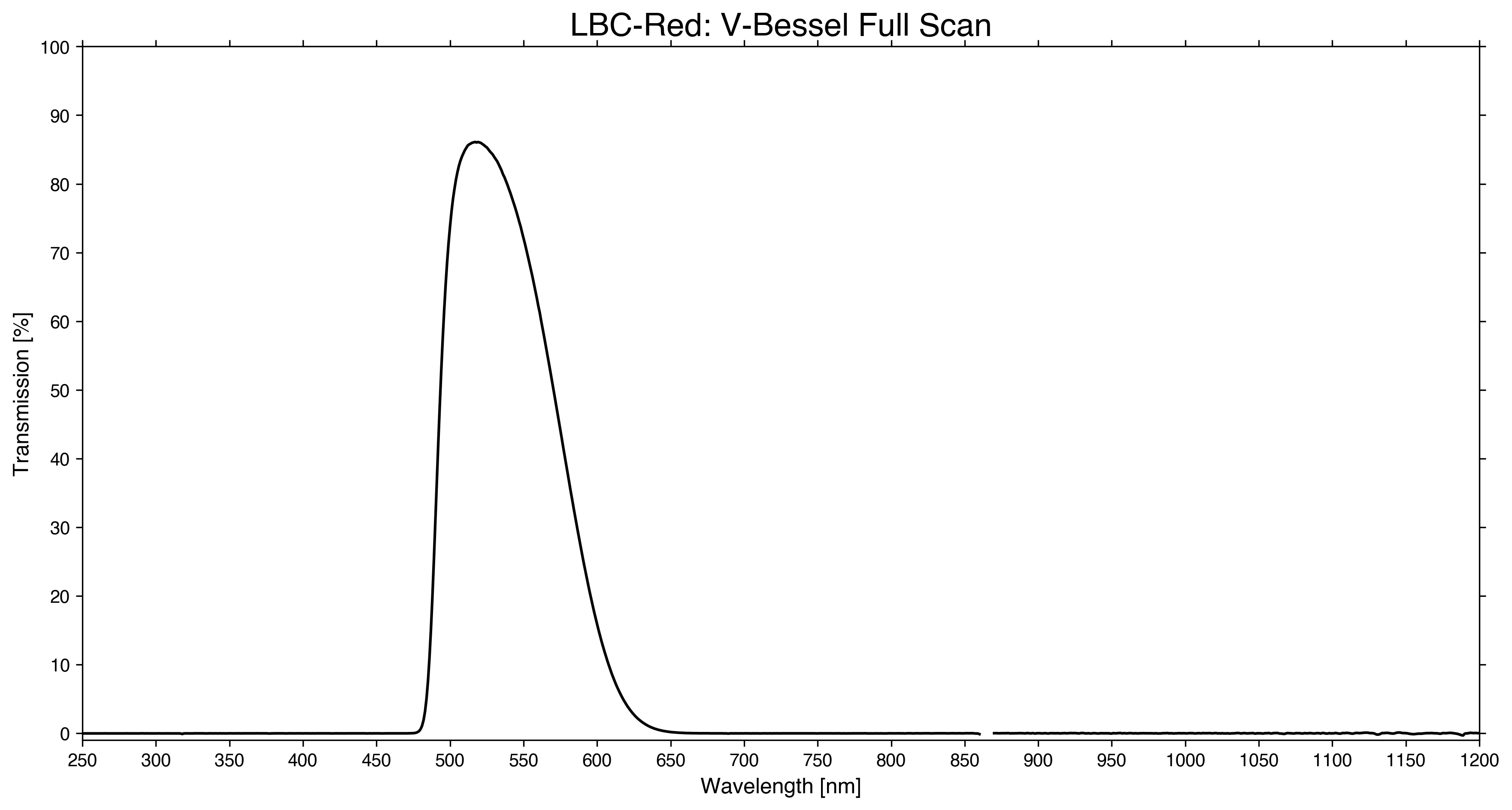
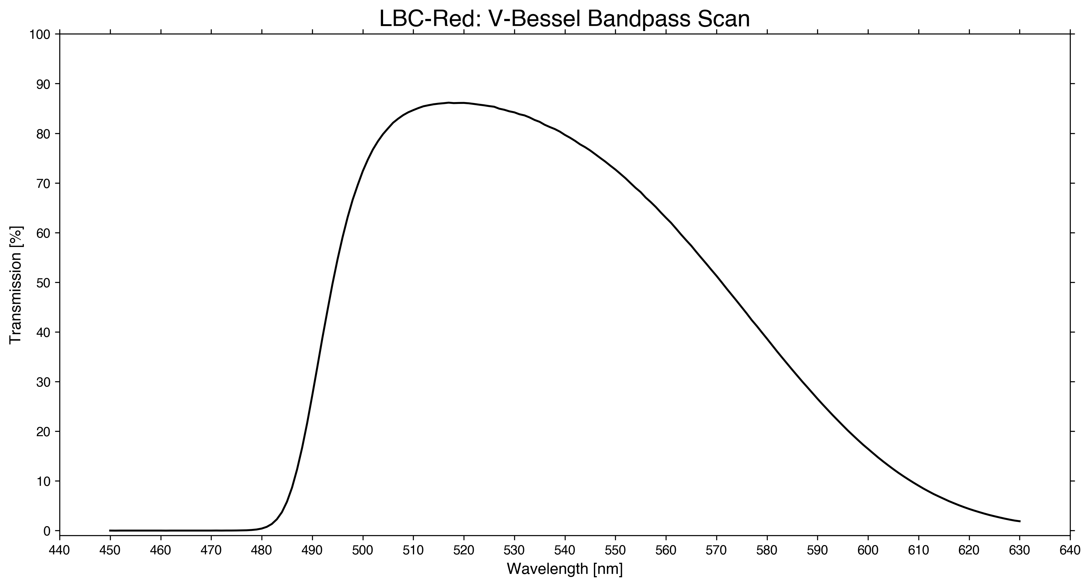
| 23 | V-Bessel | full/bandpass | full/bandpass | No | 5346.3 | 836.8 | 4927.9 | 5764.7 | 86.2% |
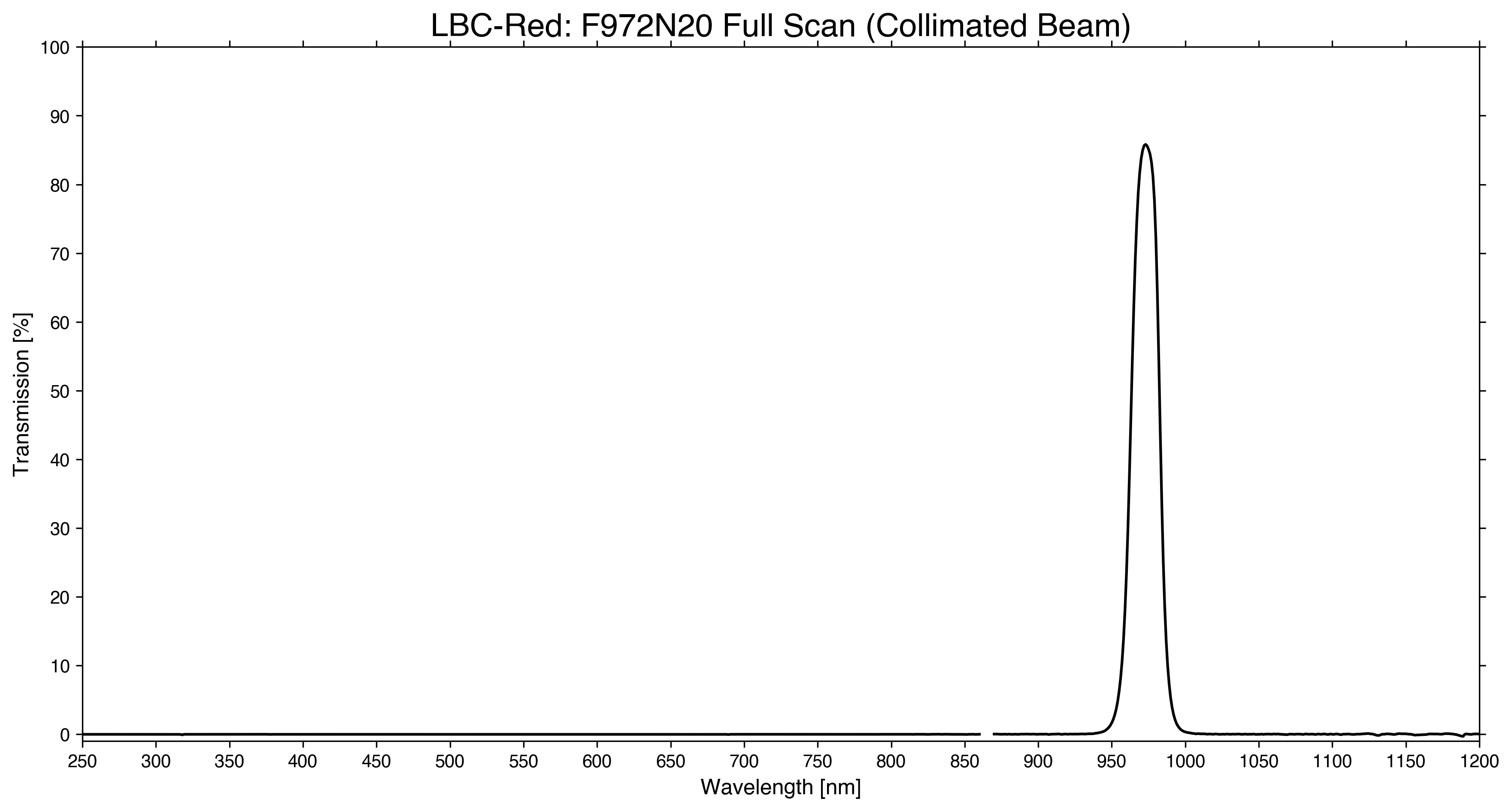
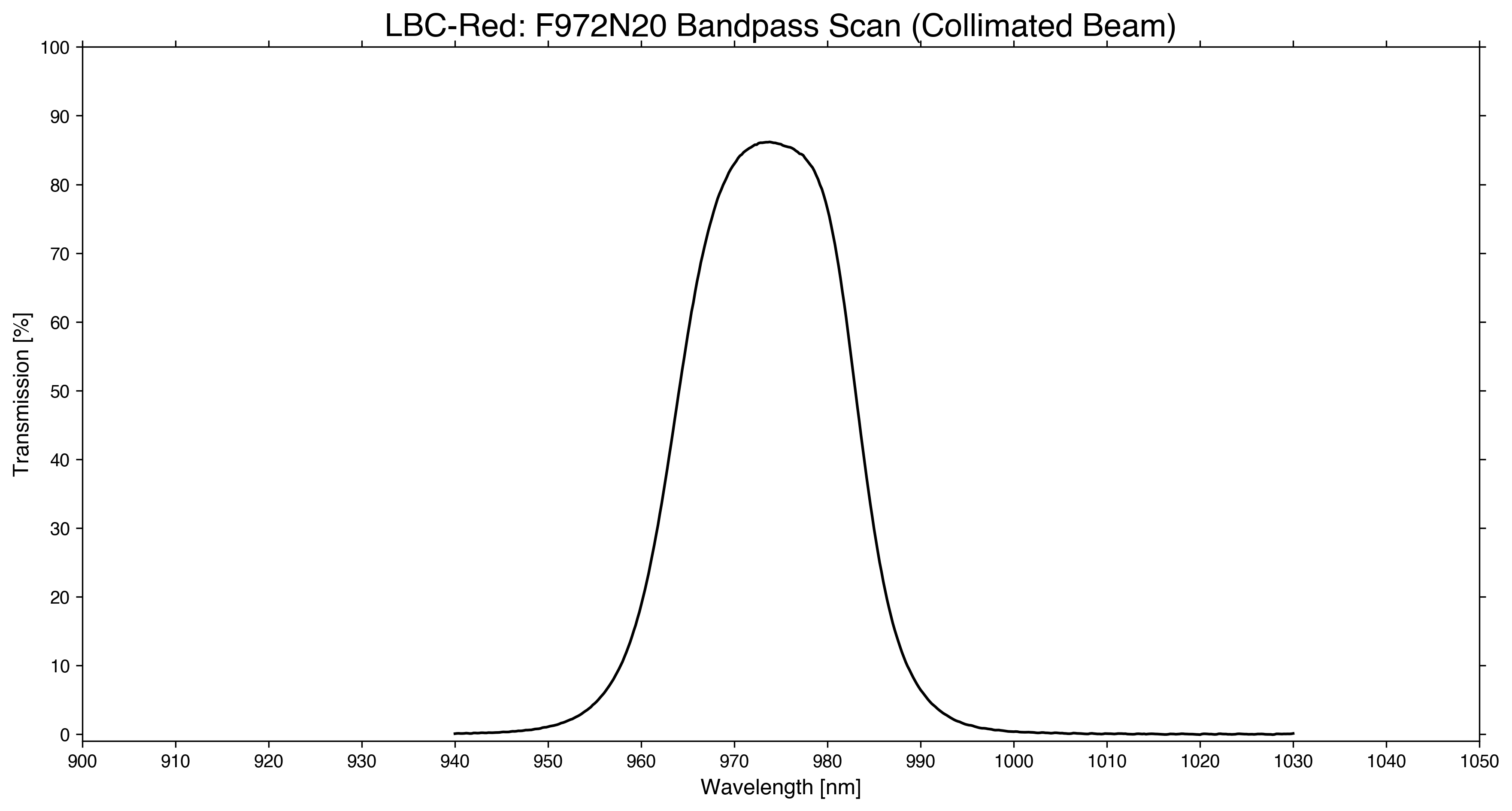
| 24 | F972N20 (coll) | full/bandpass | full/bandpass | Yes | 9734.7 | 203.4 | 9633.0 | 9836.4 | 86.2% |
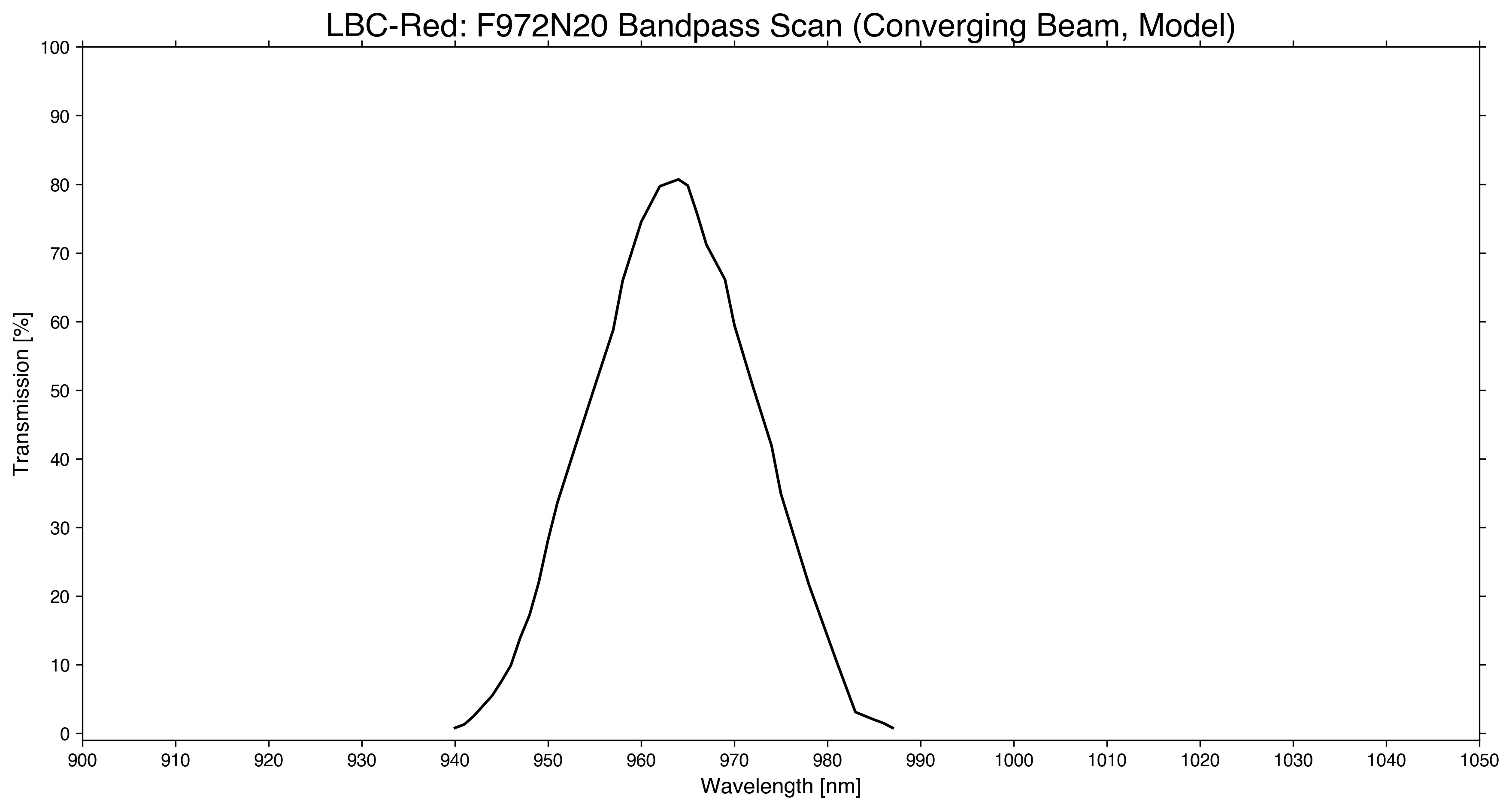
| F972N20 (conv)2 | bandpass2 | bandpass2 | 9634.0 | 216.3 | 9525.9 | 9742.2 | 80.7% | ||
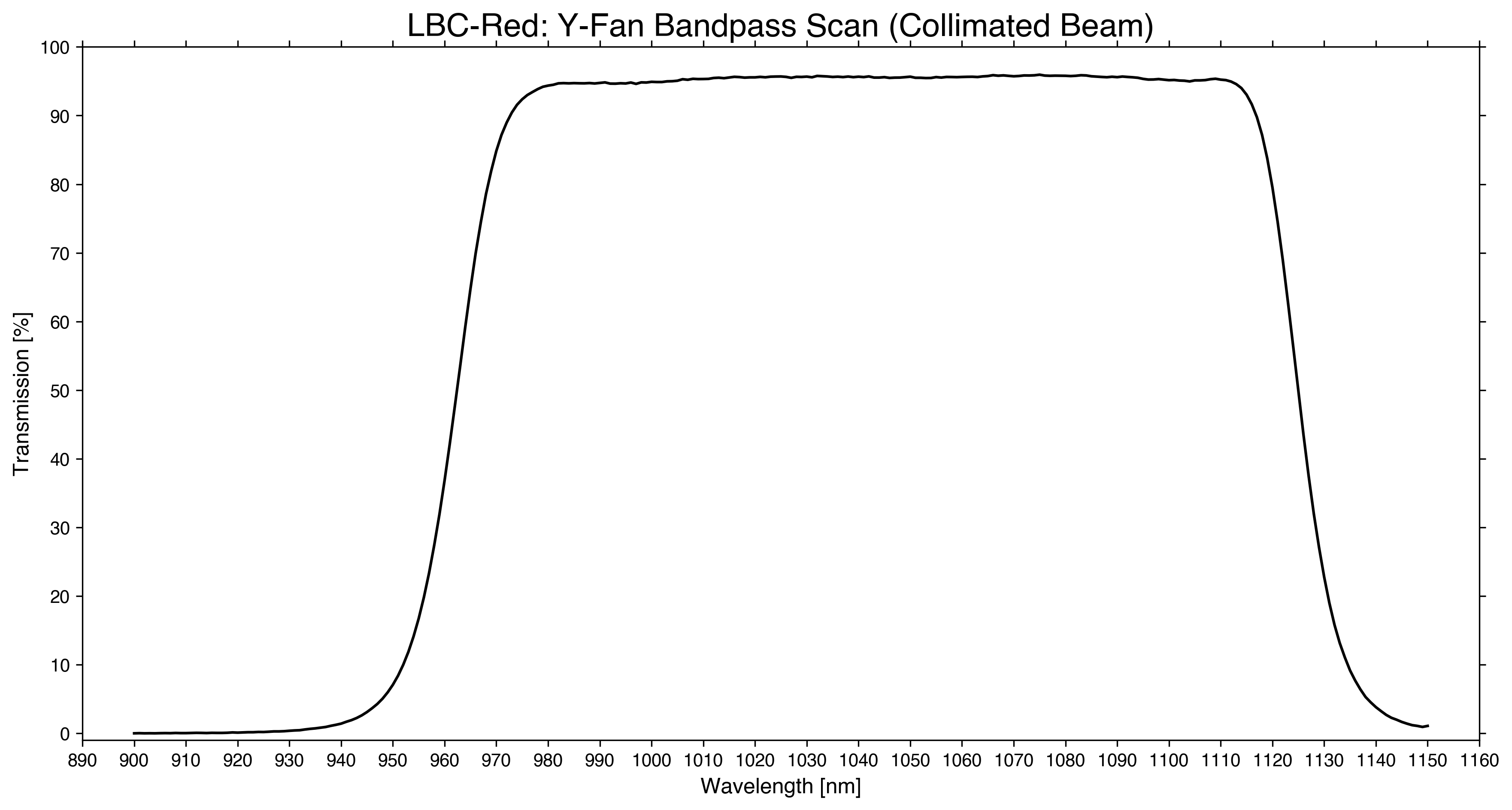
| 25 | Y-Fan | full/bandpass | full/bandpass | Yes | 10436.7 | 1632.7 | 9620.4 | 11253.1 | 96.0% |
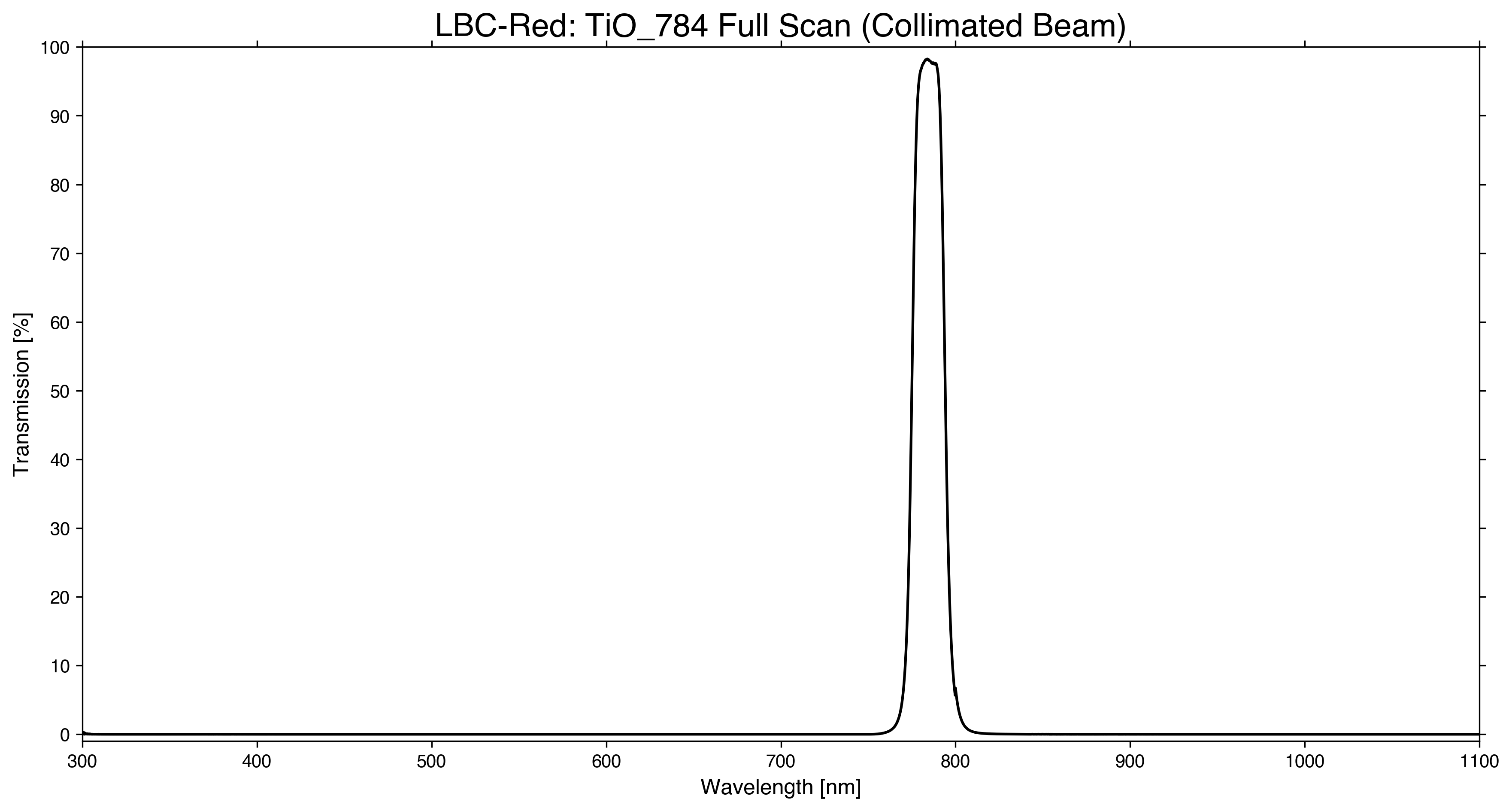
| Storage | TiO_784 (coll) | full | full | Yes | 7845.4 | 192.5 | 7749.2 | 7941.7 | 98.3% |
| TiO_784 (conv) | bandpass | bandpass | TBD | TBD | TBD | TBD | TBD | ||
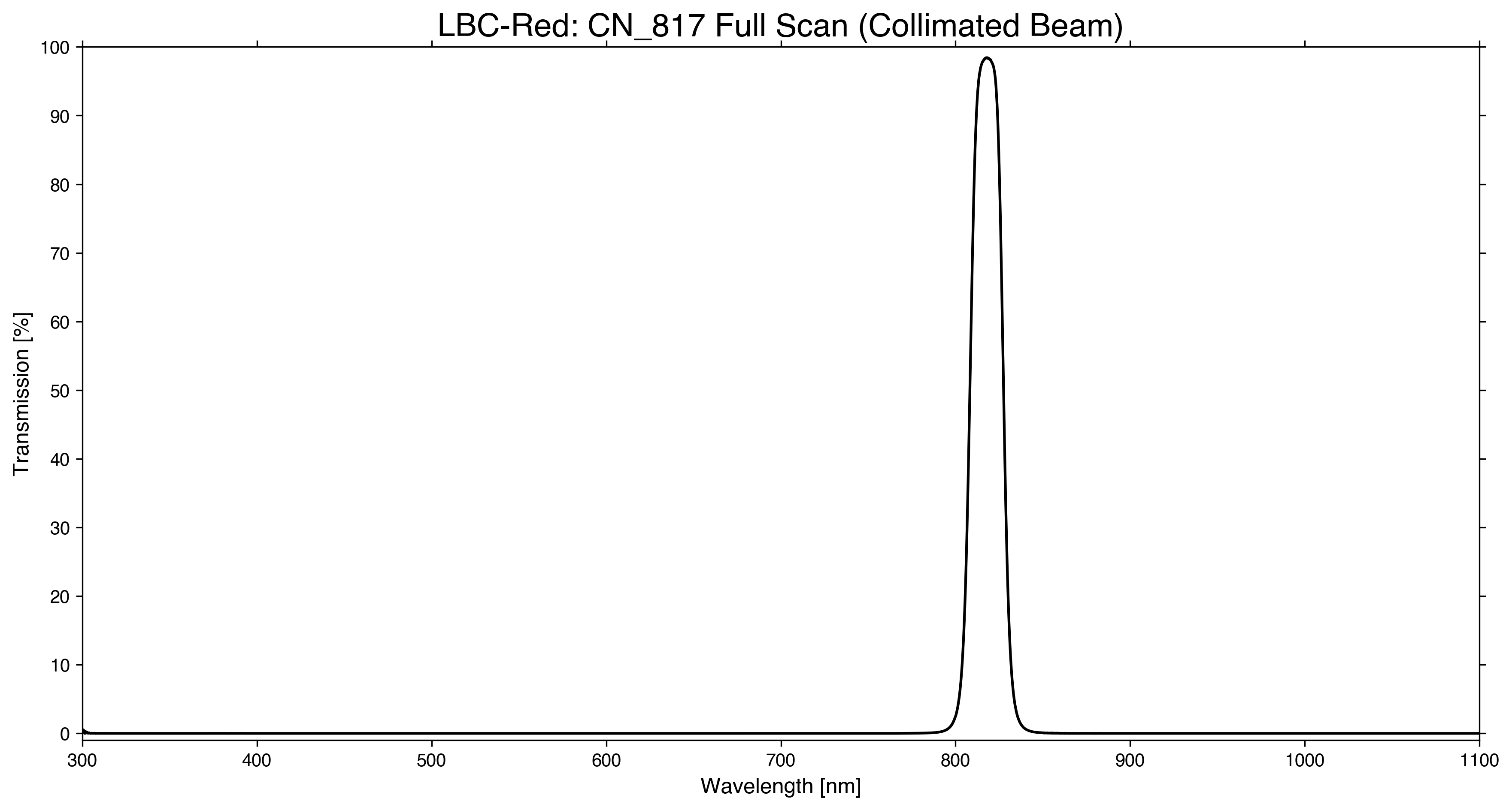
| Storage | CN_817 (coll) | full | full | Yes | 8178.6 | 194.0 | 8081.6 | 8275.6 | 98.4% |
| CN_817 (conv) | bandpass | bandpass | TBD | TBD | TBD | TBD | TBD | ||
1. There are two copies of the g-Sloan and r-Sloan filters. These spare filters were not measured in 2025 since they were never used, however their transmission is included in the old filter data table below.
2. We could not obtain the transmission through a converging beam based on the 2025 scan, however this is the modeled curve from the manufacturer in 2009. There is only a minor change in the transmission between the two scans, so we believe the modeled curve is sufficiently close.
Each filter was measured twice in a collimated beam: a full wavelength scan at high speed from 250-1200nm for any out-of-band leaks, and a slower scan over the filter bandpass. The large sizes of the filters meant that only the area of the filter closer to the edge was measured rather than the center, but this should not meaningfully affect the result. The FWHM, 50% cut-on, and 50% cut-off are listed for each filter, as well as the central wavelength (CWL) which is the midpoint between the 50% values and not where the transmission curve peaks. The first digit of the filter position denotes which wheel, 1 or 2, and the second the position, 1 through 5, in that wheel. Note that the z-Sloan filter has no red cutoff, instead it is limited by the detector QE which reaches ~0 at 1100 nm. Finally several of the filters have notable out-of-band leaks, however they are all beyond ~1100 nm or longer where the detector QE is effectively zero. These filters are r-Sloan (LBCB and LBCR), SDT_Uspec, and i-Sloan.
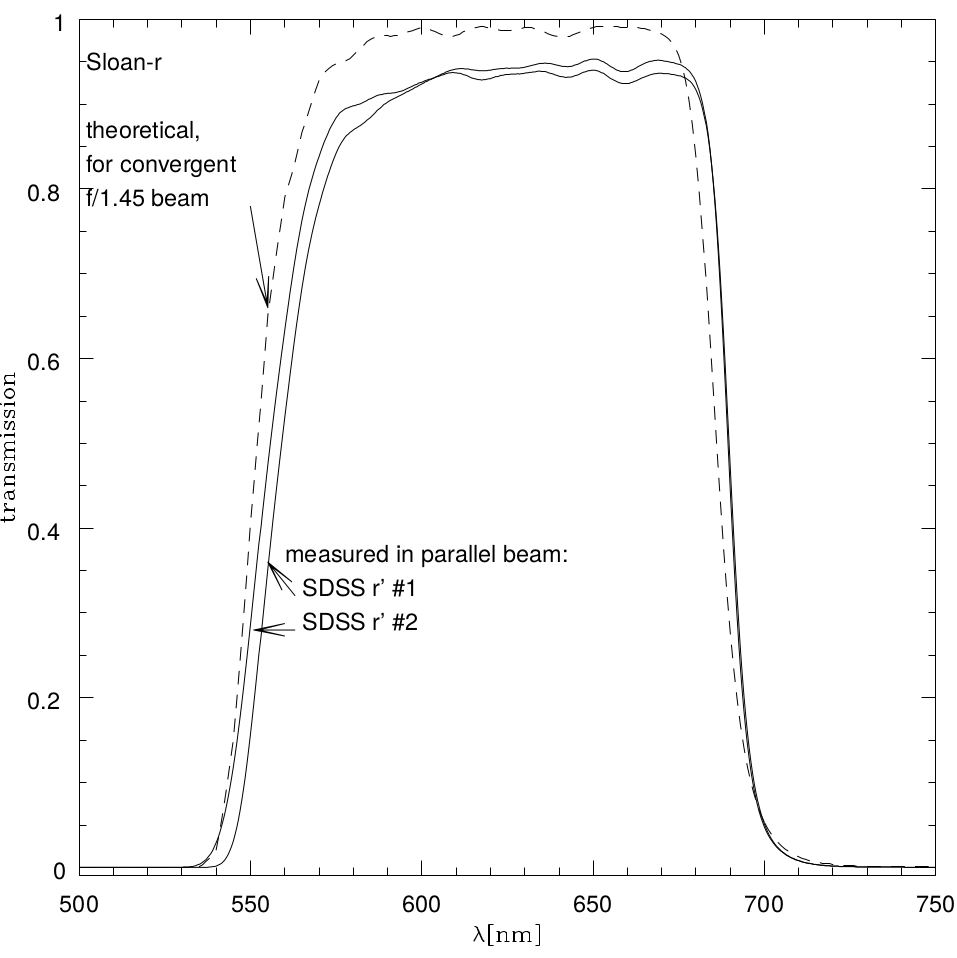
One important aspect of these filters is that they are all in the instrument’s f/1.45 converging beam. For filters that are composed entirely of colored glass (e.g. the Bessel filters) this does not change anything. However in the case of interference-based filters (e.g. the Sloan and all the narrowband filters) this makes determining the filter’s true transmission curve seen by the detector more challenging, as it shifts the response curve towards shorter wavelengths and distorts the overall shape. For a detailed discussion of this see Battaini et al. 2022 and Battaini et al. 2024. This effect is much more pronounced in the case of narrowband filters where the shift can be as high as ~10 nm. For broadband filters though we consider this effect to be small enough that it is negligible, these are the Sloan filters, SDT_USpec, and Y-Fan. Additionally only the red cutoff of these broadband filters are interference based while colored glass is used for the blue cutoff, thus any shift or distortion would only be seen on the red edge. Therefore, we adopt transmission curves derived from a collimated beam for all the broadband filters, while for the narrowband filters we include the transmission in both a collimated as well as converging beam.
Filter aging and out-of-band leaks were several concerns for the LBC filters, as they are large (160mm diameter for blue, 190mm for red) and sometimes exposed to the elements when mounted at the prime focus. In order to investigate and quantify this, we re-measured the transmission curves for all filters in 2025, except for TiO_784 and CN_817 as they are rarely mounted. Fortunately, we found very little performance degradation, with the worst being I-Bessel losing approximately a few percent in total throughput. These comparison plots (all using the collimated beam measurements) are available here, where the grey curve is the older data (noted in the title) and the black curve is from 2025. We also did not find any changes in out-of-band leaks, especially for filters with known (pre-existing from manufacturer) leaks out beyond ~1100 nm (where the detector QE is effectively zero). Again the gap between 860-870nm is due to a broken motor in the spectrometer. As above, each filter has a full scan for out-of-band leaks, and a slower scan over the bandpass. We also include the old scan data in the table below for completeness, as well as the year the data were obtained.
Old Transmission Curve Scan Data
| Filters in LBC Blue | |||||
|---|---|---|---|---|---|
| Position1 | Filter Name | 50% cut on [Angstroms] | 50% cut off [Angstroms] | Peak Trans [%] | Year Measured |
| 11 | empty | ||||
| 12 | U-BESSEL ascii |
3432 | 3773 | 65.7 | 2017 |
| 13 | V-BESSEL ascii |
4881 | 6015 | 93.1 | 2017 |
| 14 | SDT_Uspec ascii_R15 ascii_R40 ascii_R65 |
2017 | |||
| 15 | B-BESSEL ascii |
3879 | 4569 | 65.7 | 2017 |
| 21 | empty | ||||
| 22 | r-SLOAN4,5 ascii #1 ascii #2 |
5520 | 6860 | 95.3 | 2005 |
| 23 | F338N10 | 3332 | 3430 | 95.0 | 2025 |
| 24 | pinhole | ||||
| 25 | g-SLOAN4,5 ascii #1 ascii #2 |
3970 | 5500 | 94.4 | 2005 |
| Filters in LBC Red | |||||
|---|---|---|---|---|---|
| Position1 | Filter Name | 50% cut on [Angstroms] | 50% cut off [Angstroms] | Peak Trans [%] | Year Measured |
| 11 | empty | ||||
| 12 | r-SLOAN5 ascii |
5533 | 6866 | 98.3 | 2007 |
| 13 | I-BESSEL ascii |
7139 | 8803 | 96.8 | 2007 |
| 14 | i-SLOAN5 ascii |
6972 | 8369 | 96.5 | 2007 |
| 15 | z-SLOAN2,5 ascii |
8300 | N/A2 | 97.0 | 2007 |
| 21 | empty | ||||
| 22 | R-BESSEL ascii |
5755 | 6716 | 78.6 | 2007 |
| 23 | V-BESSEL ascii |
4940 | 5716 | 87.3 | 2007 |
| 24 | F972N20 ascii_meas ascii_model |
9636 | 9825 | 87.6 | 2017 |
| 25 | Y-FAN5 ascii |
9525 | 11107 | 96.3 | 2007 |
| TiO_7843 ascii |
7750 | 7941 | 98.3 | 2014 | |
| CN_8173 ascii |
8082 | 8275 | 98.4 | 2014 | |
1. The first digit denotes which wheel, 1 or 2, and the second the position, 1 through 5, in that wheel.
2. The Sloan z’ filter has no red cutoff, it is limited by detector QE which reaches ~0 at 1100nm
3. Only installed upon request.
4. There are two copies of the g-SLOAN and r-SLOAN filters in LBCB. The one marked #1 is installed and #2 is the spare.
5. These interference filters were measured in a collimated beam, but the cut on and cut off values in this table were corrected for a convergent beam as is the case for the LBCs.
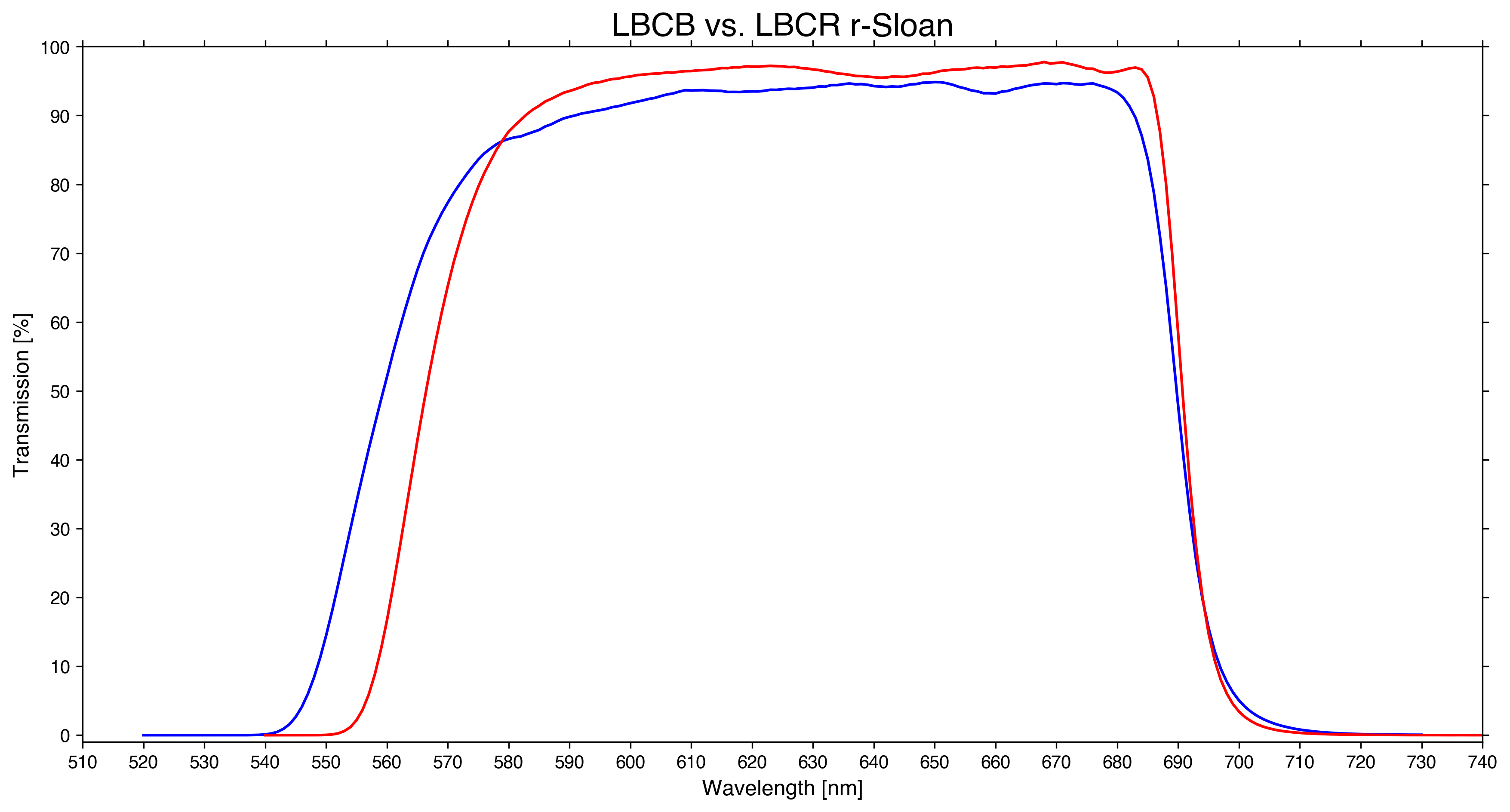
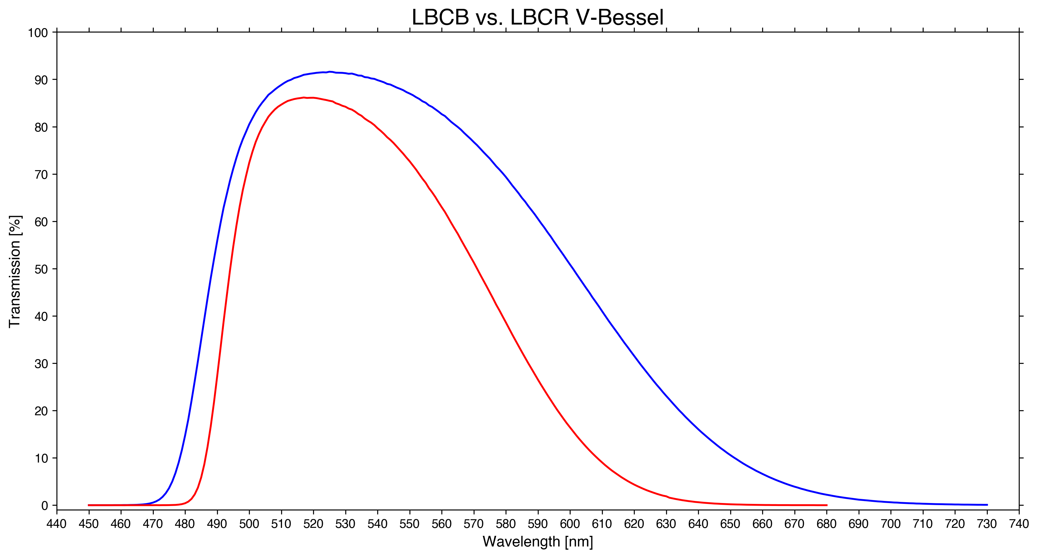
Common Filters Between LBCB and LBCR
Finally there are two filters that are common to both LBC-Blue and LBC-Red, these are the r-Sloan and V-Bessel filters. It should noted however that the total throughput and hence sensitivity is still different despite them nominally being identical filters. In the case of r-Sloan, both of their filter responses are quite similar since both were manufactured by Asahi Spectra Co. However there are two key differences, (1) the glass used in each LBC’s field lenses were optimized for either bluer (fused silica) or redder (Schott BK7) wavelengths and thus have different transmission fractions, and (2) each detector’s QE was also optimized for either bluer or redder wavelengths. To demonstrate this simultaneous r-Sloan/r-Sloan flats have a count difference of about red/blue=1.15x (exposure times were the same for each corresponding image). For V-Bessel in addition the filter responses are quite different, with red having an overall lower transmission than on blue side. This is mainly because each filter was produced by a different manufacturer (Gestione SILO for blue, Asahi Spectra Co. for red). Below we show the transmission curves for each common filter.